RM0440 Rev 4 1809/2126
RM0440 Serial audio interface (SAI)
1858
Enabling the PDM interface
To enable the PDM interface, follow the sequence below:
1. Configure SAI_A in TDM master mode (see Table 366).
2. Configure the PDM interface as follows:
a) Define the number of digital microphones via MICNBR.
b) Enable the bitstream clock needed in the application by setting the corresponding
bits on CKEN to 1.
3. Enable the PDM interface, via PDMEN bit.
4. Enable the SAI_A.
Note: Once the PDM interface and SAI_A are enabled, the first 2 TDMA frames received on
SAI_ADR are invalid and shall be dropped.
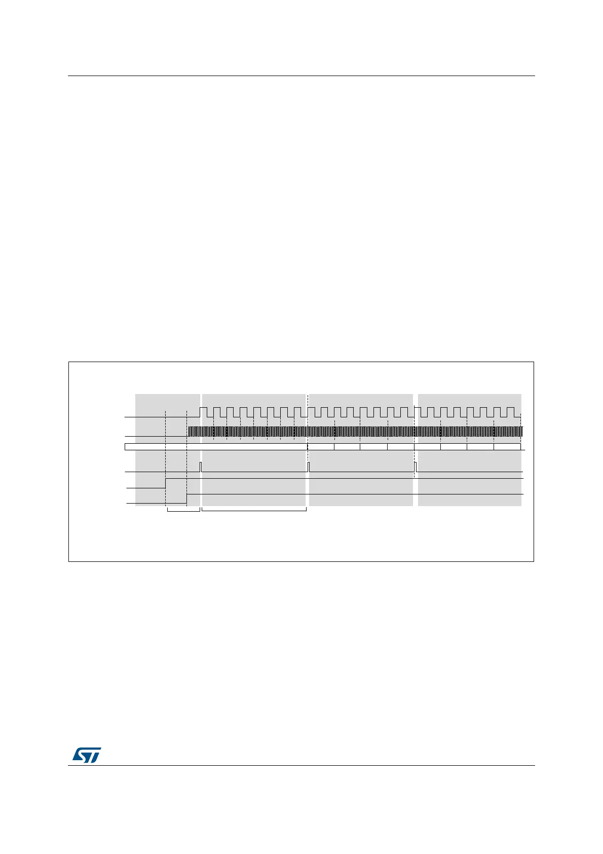
Start-up sequence
Figure 617 shows the start-up sequence: Once the PDM interface is enabled, it waits for the
frame synchronization event prior to starting the acquisition of the microphone samples.
After 8 SAI_CK clock periods, a data byte coming from each microphone is available, and
transferred to the SAI, via the TDM interface.
Figure 617. Start-up sequence
SAI_ADR data format
The arrangement of the data coming from the microphone into the SAI_ADR register
depends on the following parameters:
• The amount of microphones
• The slot width selected
• LSBFIRST bit.
The slot width defines the amount of significant bits into each word available into the
SAI_ADR.
When a slot width of 32 bits is selected, each data available into the SAI_ADR will contain
32 useful bits. This reduces the amount of words stored into the memory. However the
MSv35469V3
Don’t care
8 bits
123 4567 8 123 4567 8 123 4567 8
Frame sync is detected, waiting
for receiving 8 bits from each
microphone
Transmission to SAI of the data received
on frame N, and acquisition of the next
8 bits from each microphone.
No re-sync with the frame sync
N N+1 N+2
Transmission to SAI of the data received
on frame N+1, and acquisition of the next
8 bits from each microphone.
No re-sync with the frame sync
M1L-x M1R-x M2L-x M2R-x M1L-y M1R-y M2L-y M2R-y
Wait for frame
sync.
saia_clk_out
saia_sd_in
saia_fs_out
PDMEN
SAIEN
Pdm_ck
8 bits 8 bits 8 bits 8 bits 8 bits 8 bits 8 bits
 Loading...


