RM0440 Rev 4 735/2126
RM0440 Digital-to-analog converter (DAC)
773
• Dual DAC channels (when available)
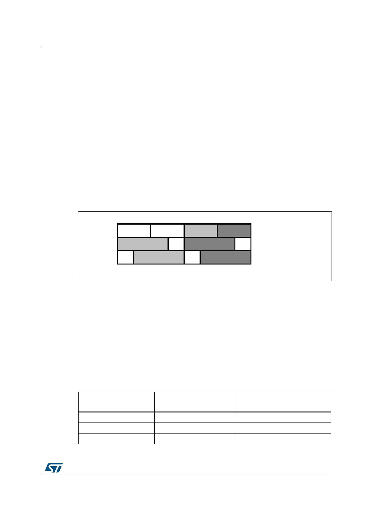
There are three possibilities:
– 8-bit right alignment: data for DAC channel1 to be loaded into the DAC_DHR8RD
[7:0] bits (stored into the DHR1[11:4] bits) and data for DAC channel2 to be loaded
into the DAC_DHR8RD [15:8] bits (stored into the DHR2[11:4] bits)
– 12-bit left alignment: data for DAC channel1 to be loaded into the DAC_DHR12LD
[15:4] bits (stored into the DHR1[11:0] bits) and data for DAC channel2 to be
loaded into the DAC_DHR12LD [31:20] bits (stored into the DHR2[11:0] bits)
– 12-bit right alignment: data for DAC channel1 to be loaded into the
DAC_DHR12RD [11:0] bits (stored into the DHR1[11:0] bits) and data for DAC
channel2 to be loaded into the DAC_DHR12RD [27:16] bits (stored into the
DHR2[11:0] bits)
Depending on the loaded DAC_DHRyyyD register, the data written by the user is shifted
and stored into DHR1 and DHR2 (data holding registers, which are internal non-memory-
mapped registers). The DHR1 and DHR2 registers are then loaded into the DAC_DOR1
and DOR2 registers, respectively, either automatically, by software trigger or by an external
event trigger.
Figure 158. Data registers in dual DAC channel mode
Signed/unsigned data
DAC input data are unsigned: 0x000 corresponds to the minimum value and 0xFFF to the
maximum value for 12-bit mode.
The DAC can also handle signed input data in 2’s complement format. This is done by
setting SINFORMATx bit in the DAC_MCR register.
When SINFORMATx bit is set, the MSB bit of the data written to DHRx registers is inverted
when it is copied to the DAC_DORx register, and the DAC interface can accept signed data
(Q1.15, Q1.11 or Q1.7 format). DAC_DHR12Lx register can be used to store 16-bit signed
data in the data holding registers. The 12 MSBs of 16-bit data are used for the DAC output
data and the MSB bit is inverted. The four LSBs are simply ignored.
Table 186. Data format (case of 12-bit data)
SINFORMATx bit
DATA written to DHRx
register
DATA transfered to DORx register
0 0x000 0x000
0 0xFFF 0xFFF
1 0x7FF 0xFFF
31 24 15 7 0
8-bit right aligned
12-bit left aligned
12-bit right aligned
ai14709b