RM0440 Rev 4 1161/2126
RM0440 Advanced-control timers (TIM1/TIM8/TIM20)
1226
register. A transition error interrupt will be generated if the TERRIE bit is set in the
TIMx_DIER register.
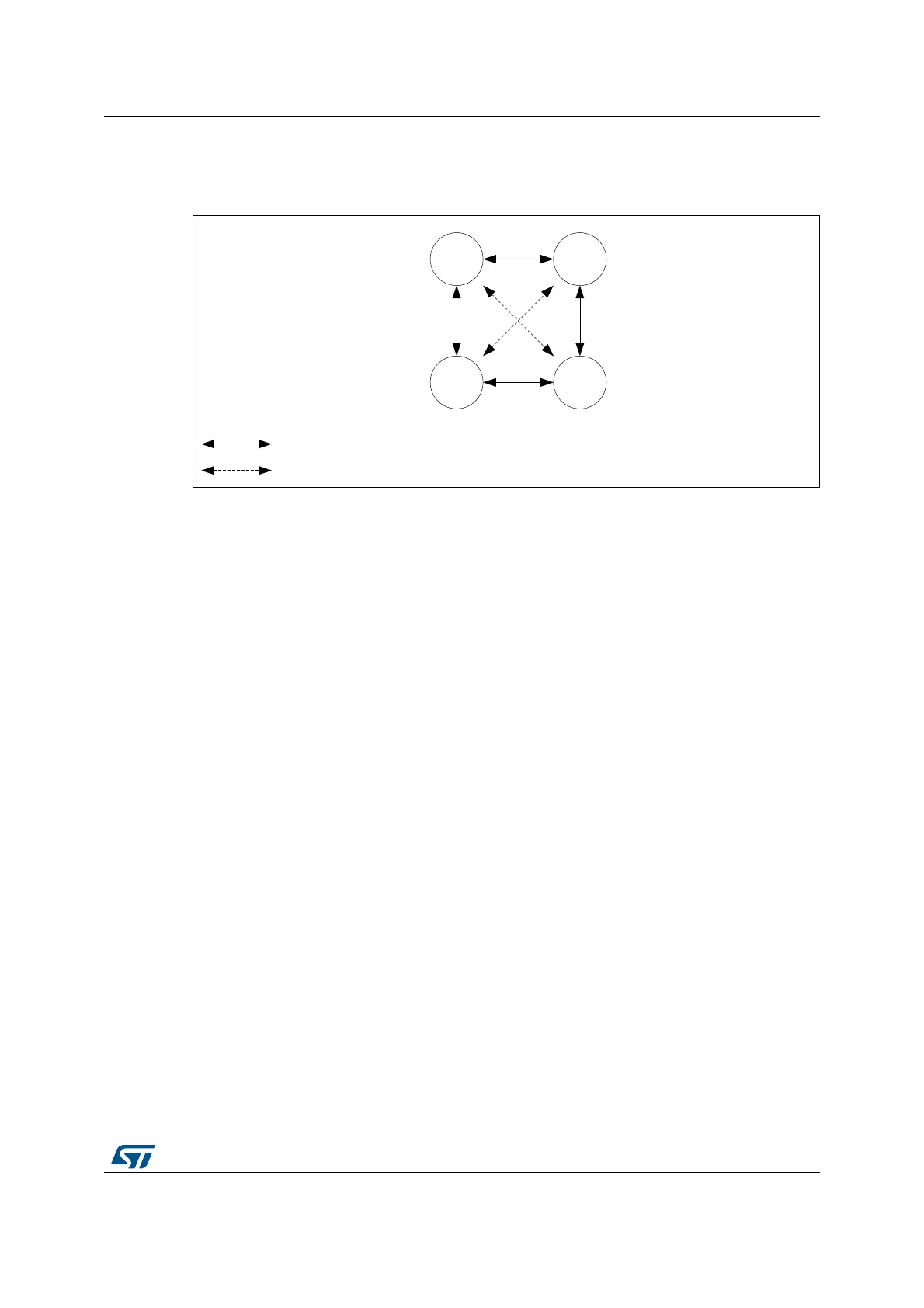
Figure 348. State diagram for quadrature encoded signals
For encoder having an Index signal, it is possible to detect abnormal operation resulting in
an excess of pulses per revolution. An encoder with N pulses per revolution will provide 4xN
counts per revolution. The Index signal will reset the counter every 4xN clock periods.
If the counter value is incremented from TIMx_ARR to 0 or decremented from 0 to TIMxARR
value without any index event, this will be reported as an Index position error.
The overflow threshold is programmed using the TIMx_ARR register. A 1000 lines encoder
will result in a counter value being between 0 and 3999 (in 4x reading mode). The overflow
detection threshold must be programmed by setting TIMx_ARR = 3999 + 1 = 4000.
MSv45779V1
00 01
1110
Correct transitions
Erroneous transitions
 Loading...


