Serial audio interface (SAI) RM0440
1812/2126 RM0440 Rev 4
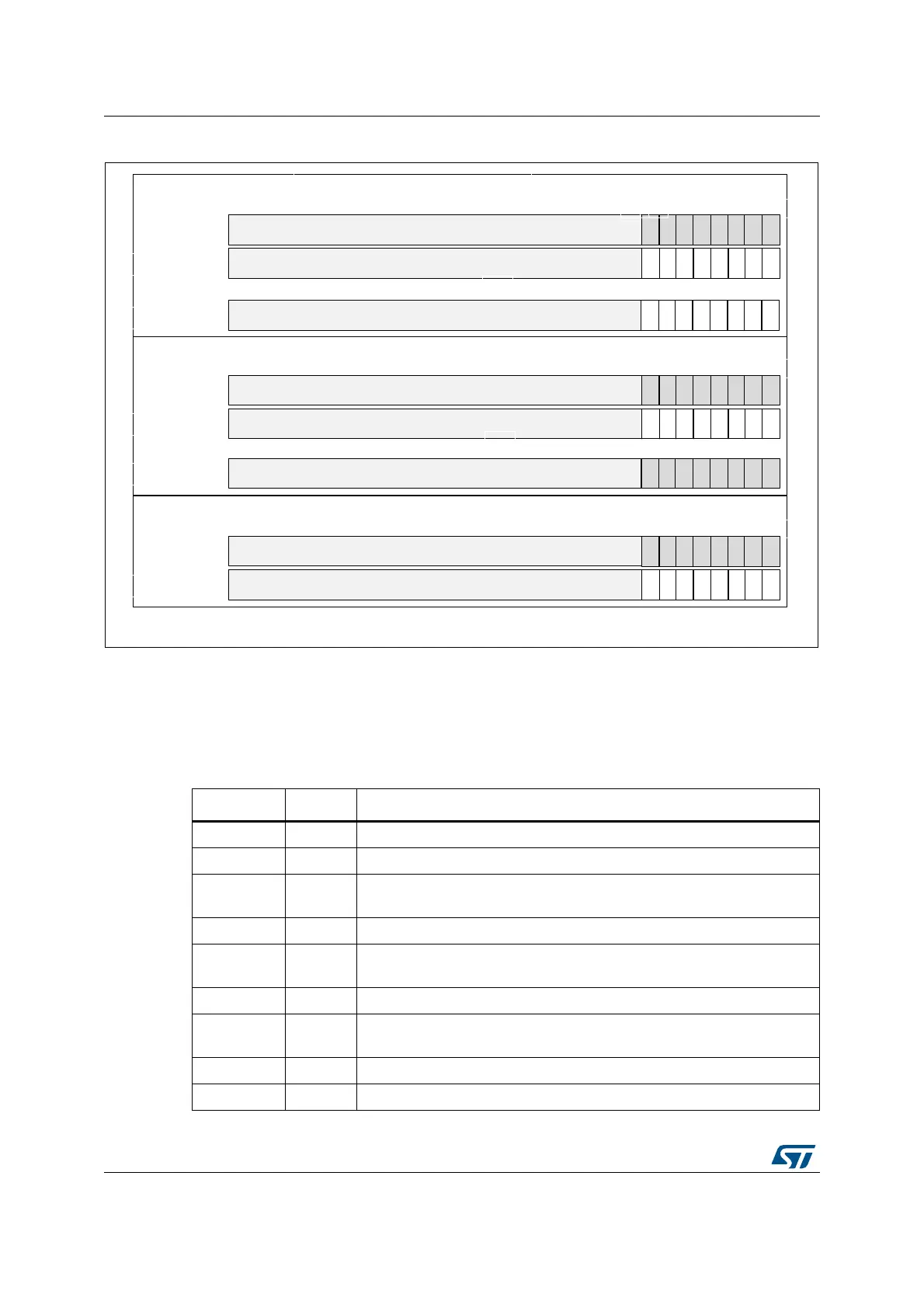
Figure 620. SAI_ADR format in TDM, 8-bit slot width
TDM configuration for PDM interface
SAI_A TDM interface is internally connected to the PDM interface to get the microphone
samples. The user application must configure the PDM interface as shown in Table 366 to
ensure a good connection with the PDM interface.
MSv35472V1
b31 b0
M4R-1
M4R-2
M4R-3
M4R-4
M4R-5
M4R-6
M4R-7
M4R-8
LSBFIRST = 0
word 8n
word 8n+7
8 Microphones configuration
b31 b0
LSBFIRST = 0
4 Microphones configuration
b31 b0
LSBFIRST = 0
2 Microphones configuration
M1L-1
M1L-2
M1L-3
M1L-4
M1R-1
M1R-2
M1R-3
M1R-4
M1L-5
M1L-6
M1L-7
M1L-8
M1R-5
M1R-6
M1R-7
M1R-8
zeros
zeros
zeros
...
word 8n+1
M2R-1
M2R-2
M2R-3
M2R-4
M2R-5
M2R-6
M2R-7
M2R-8
word 4n+3
b7b8
zeros
word 4n
M1L-1
M1L-2
M1L-3
M1L-4
M1R-1
M1R-2
M1R-3
M1R-4
M1L-5
M1L-6
M1L-7
M1L-8
M1R-5
M1R-6
M1R-7
M1R-8
zeros
zeros
...
word 4n+1
word 2n
M1L-1
M1L-2
M1L-3
M1L-4
M1R-1
M1R-2
M1R-3
M1R-4
M1L-5
M1L-6
M1L-7
M1L-8
M1R-5
M1R-6
M1R-7
M1R-8
zeros
zeros
word 2n+1
Table 366. TDM settings
Bit Fields Values Comments
MODE 0b01 Mode must be MASTER receiver
PRTCFG 0b00 Free protocol for TDM
DS X
To be adjusted according to the required data format, in accordance to the
frame length and the number of slots (FRL and NBSLOT). See Table 367.
LSBFIRST X This parameter can be used according to the wanted data format
CKSTR 0
Signal transitions occur on the rising edge of the SCK_A bit clock. Signals
are stable on the falling edge of the bit clock
.
MONO 0 Stereo mode
FRL X
To be adjusted according to the number of microphones (MICNBR). See
Table 367.
FSALL 0 Pulse width is one bit clock cycle
FSDEF 0 FS signal is a start of frame
 Loading...


