RM0440 Rev 4 2057/2126
RM0440 USB Type-C™ / USB Power Delivery interface (UCPD)
2079
The events causing the wakeup can be:
• Events on the BMC receiver (RXORDDET, RXHRSTDET), hardware enable
PHYRXEN
• Event on the FRS detector (FRSEVT), hardware enable FRSRXEN
• Events on the Type-C detectors (TYPECEVT1, TYPECEVT2), hardware enables
CC1TCDIS, CC2TCDIS
46.4.11 UCPD programming sequences
The normal sequence of use of the UCPD unit is:
1. Configure UCPD.
2. Enable UCPD.
3. Concurrently:
– On demand from protocol layer, send Tx message
– Intercept (poll or wait for interrupt) relevant Rx messages and recover detail to
hand off to protocol layer
Repeat the last point infinitely.
Initialization phase
Use the following sequence for a clean startup:
1. Prepare all initial clock divider values, by writing the UCPD_CFG register.
2. Enable the unit, by setting the UCPDEN bit.
Type-C state machine handling
For the general application cases of source, sink, or dual-role port (the last alternating the
source and the sink), the software must implement a corresponding USB Type-C state
machine. The basic coding is in the following table.
The CCENABLE[1:0] bitfield can disable pull-up/pull-downs on one of the CC lines.
Note: The Type-C state machine depends not only on CC line levels, but also on VBUS presence
detection (sink mode) and when in source mode determines VCONN generation and VBUS
state (ON/OFF/+voltage level); discharge). UCPD does not directly control VBUS
generation circuitry nor VCONN load switch (enabling VCONN supply generator to be
connected to the CC line), but the application needs these inputs and controls to function
correctly.
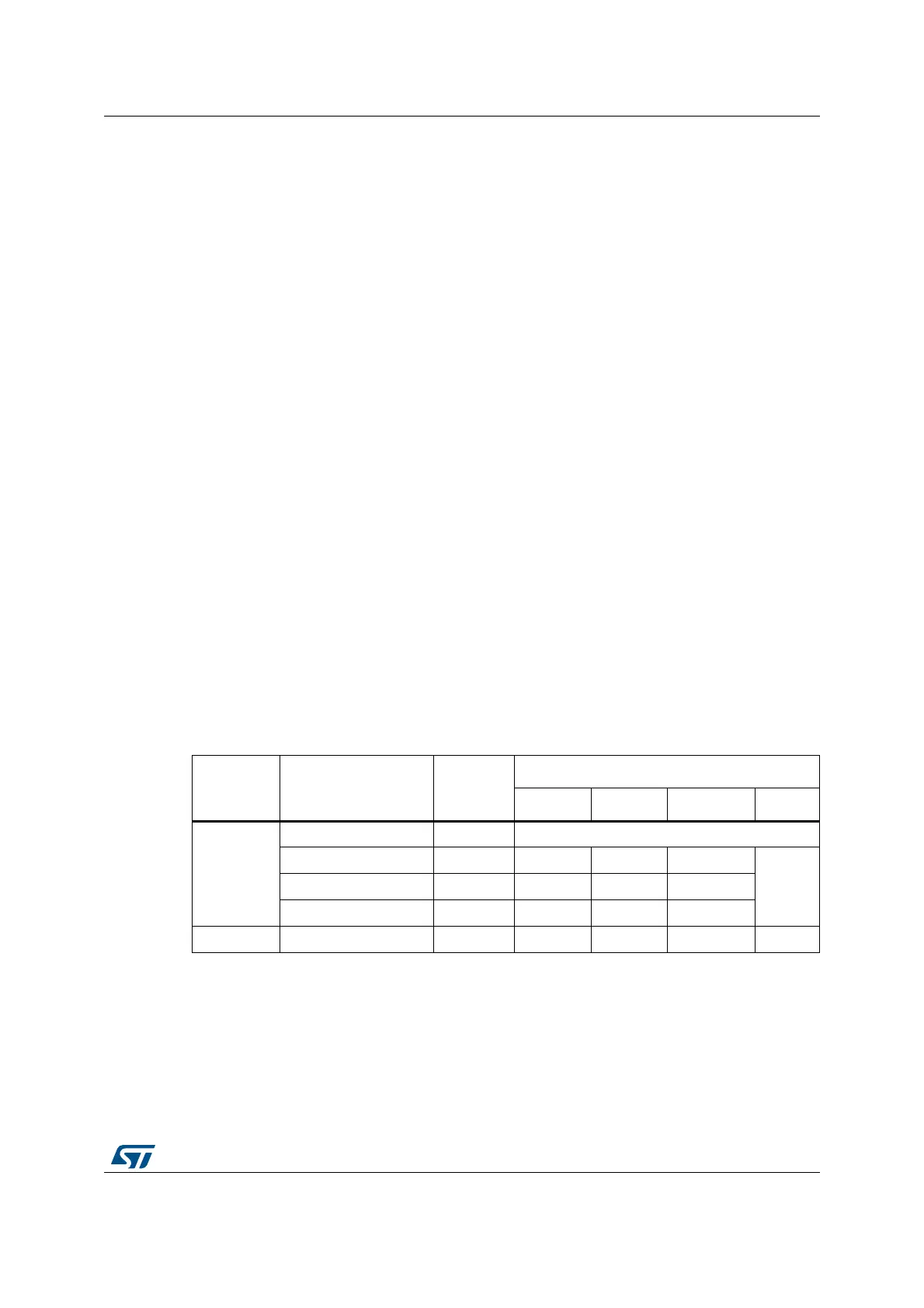
Table 425. Coding for ANAMODE, ANASUBMODE and link with TYPEC_VSTATE_CCx
ANAMODE ANASUBMODE[1:0] Notes
TYPEC_VSTATE_CCx[1:0]
00 01 10 11
0: Source
00: Disabled Disabled N/A
01: Default USB Rp - vRa[Def] vRd[Def] vOPEN[Def]
N/A10: 1.5A Rp - vRa[1.5] vRd[1.5] vOPEN[1.5]
11: 3.0A Rp - vRa[3.0] vRd[3.0] vOPEN[3.0]
1: Sink xx - vRa vRd-USB vRd-1.5 vRd-3.0
 Loading...


