RM0440 Rev 4 925/2126
RM0440 High-resolution timer (HRTIM)
1083
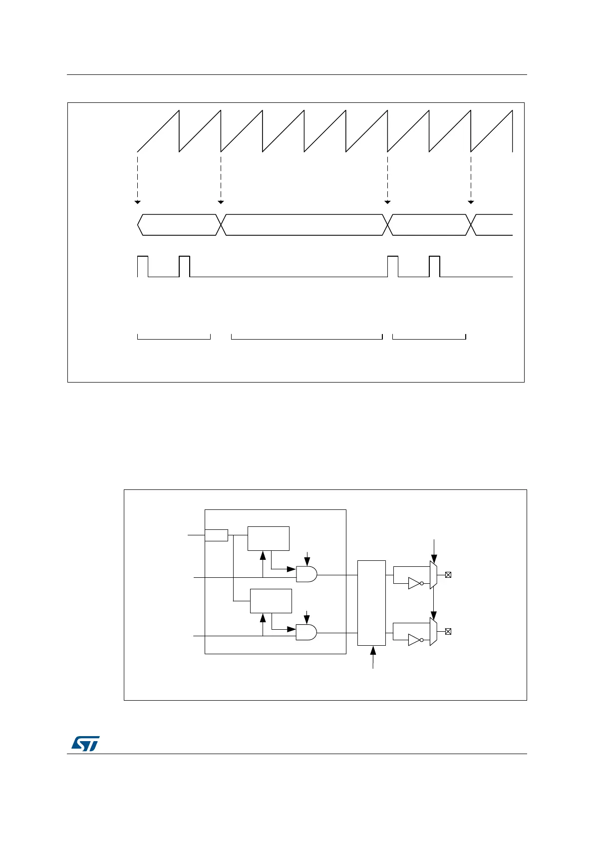
Figure 241. Burst mode emulation example
27.3.16 Chopper
A high-frequency carrier can be added on top of the timing unit output signals to drive
isolation transformers. This is done in the output stage before the polarity insertion, as
shown on Figure 242, using CHP1 and CHP2 bits in the HRTIM_OUTxR register, to enable
chopper on outputs 1 and 2, respectively.
Figure 242. Carrier frequency signal insertion
MS32288V1
Counter
Output
CMPC1xR
0x0001 0800 0x0003 0000 0x0001 0800
REP
DMA
request
REP
DMA
request
REP
DMA
request
REP
DMA
request
REPxR =1
CMP1xR = 0x0800
REPxR =3
CMP1xR = 0x0000
REPxR =1
CMP1xR = 0x0800
RUN IDLE (emulated) RUN
MS32334V2
Fault
/16
f
HRTIM
Fault / Idle sources
Polarity
x1
x2
Sync
Sync
/
Idle
CHP1
Chopper
CHP2
HRTIM_CHx2
HRTIM_CHx1
Carrier
generation
Carrier
generation
 Loading...


