RM0440 Rev 4 1153/2126
RM0440 Advanced-control timers (TIM1/TIM8/TIM20)
1226
state combination) the index must be synchronized, using the IPOS[1:0] bitfield in the
TIMx_ECR register.
The Index detection event will act differently depending on counting direction to ensure
symmetrical operation during speed reversal:
• The counter is reset during up-counting (DIR bit = 0).
• The counter is set to TIMx_ARR when down counting.
This allows the index to be generated on the very same mechanical angular position
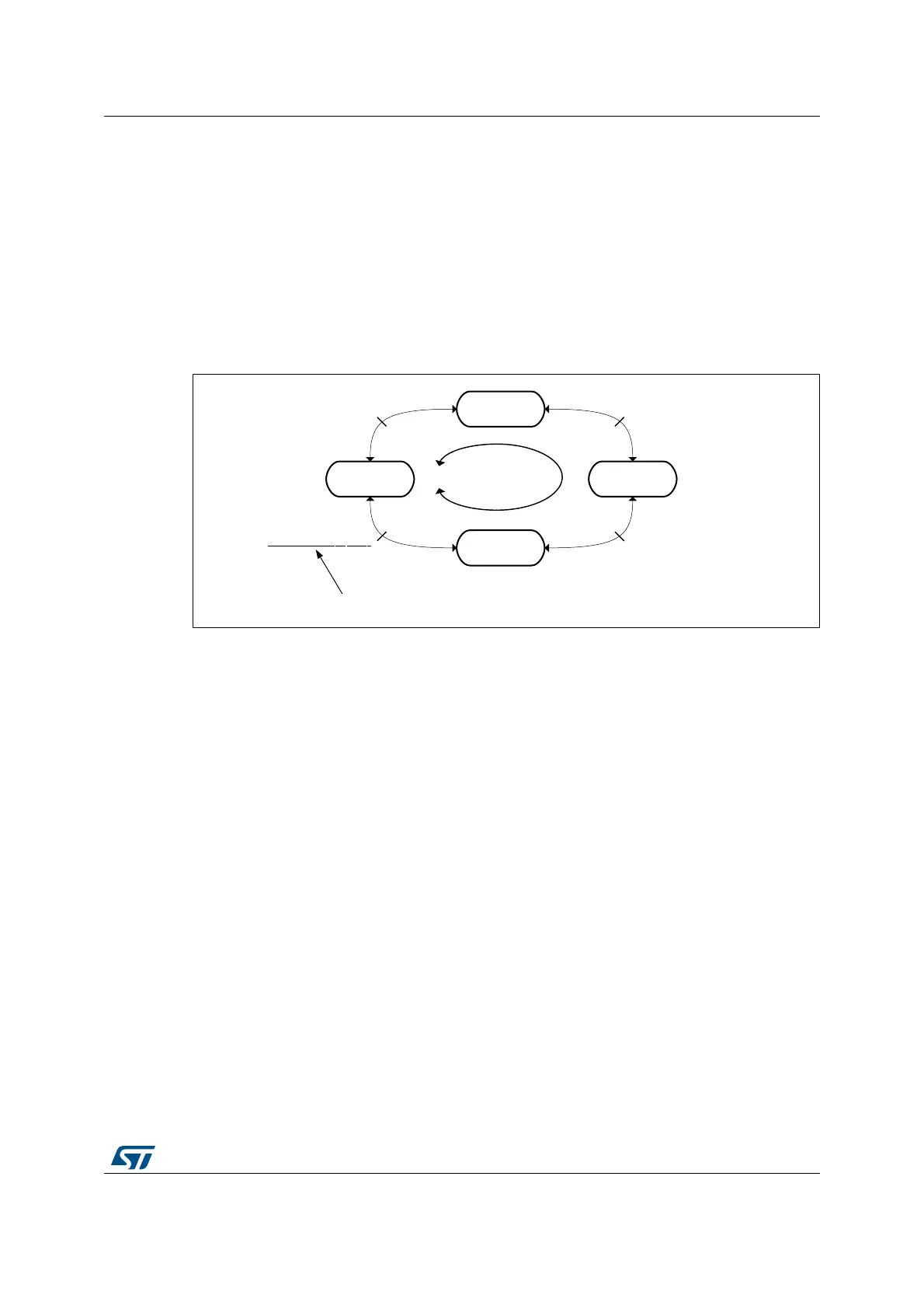
whatever the counting direction. The Figure 337 below shows at which position is the index
generated, for a simplistic example (an encoder providing 4 edges par mechanical rotation).
Figure 337. Index generation for IPOS[1:0] = 11
The Figure 338 below presents waveforms and corresponding values for IPOS[1:0] = 11. It
shows that the instant at which the counter value is forced is automatically adjusted
depending on the counting direction:
• Counter set to 0 when encoder state is '11' (ChA=1, ChB=1), when up-counting (DIR bit
= 0).
• Counter set to TIMx_ARR when exiting the '11' state, when down-counting (DIR bit =
1).
An interrupt can be issued upon index detection event.
The arrows are indicating on which transition is the index event interrupt generated.
MSv45767V1
AB = 00
State 1
AB = 01
State 2
AB = 10
State 4
AB = 11
State 3
Rotor angle = 0°
Rotor angle = 90°
Rotor angle = 180°
Rotor angle = 270°
Up-counting
Down-counting
The index event is always generated here
 Loading...


