General-purpose timers (TIM2/TIM3/TIM4/TIM5) RM0440
1246/2126 RM0440 Rev 4
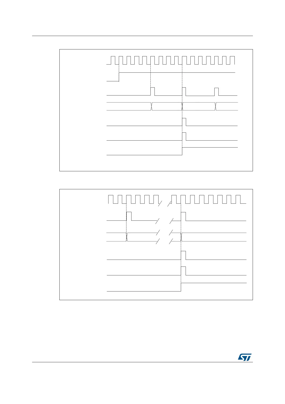
Figure 374. Counter timing diagram, internal clock divided by 4, TIMx_ARR=0x36
1. Center-aligned mode 2 or 3 is used with an UIF on overflow.
Figure 375. Counter timing diagram, internal clock divided by N
MSv62312V1
0034 0035
tim_psc_ck
tim_cnt_ck
Counter register
Update event (UEV)
Counter overflow
Update interrupt flag
(UIF)
CEN
Note: Here, center_aligned mode 2 or 3 is updated with an UIF on overflow
0036 0035
MSv62313V1
00
1F
20
tim_psc_ck
tim_cnt_ck
Counter register
Update event (UEV)
Counter underflow
Update interrupt flag
(UIF)
01
 Loading...


