Analog-to-digital converters (ADC) RM0440
666/2126 RM0440 Rev 4
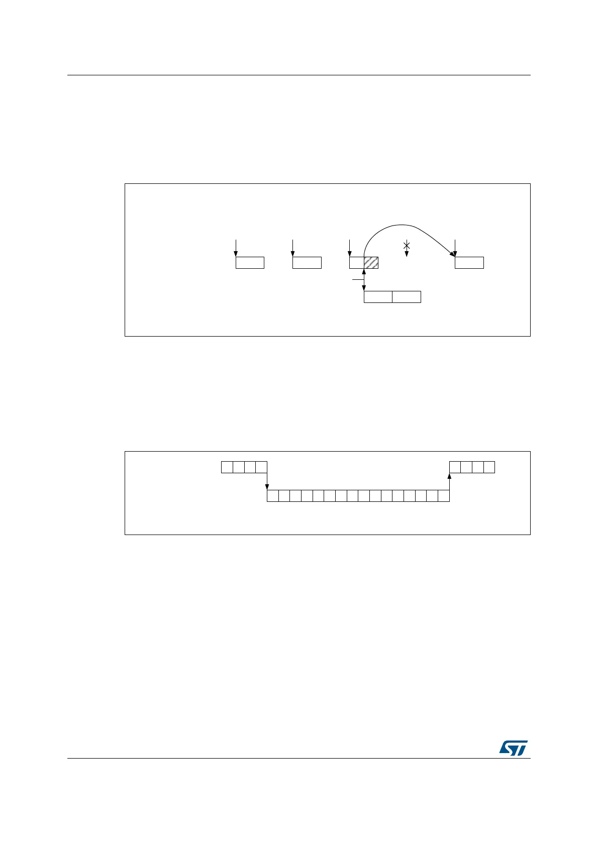
Triggered regular oversampling with injected conversions
It is possible to have triggered regular mode with injected conversions. In this case, the
injected mode oversampling mode must be disabled, and the ROVSM bit is ignored
(resumed mode is forced). The JOVSE bit must be reset. The behavior is represented on
Figure 135 below.
Figure 135. Triggered regular oversampling with injection
Auto-injected mode
It is possible to oversample auto-injected sequences and have all conversions results stored
in registers to save a DMA resource. This mode is available only with both regular and
injected oversampling active: JAUTO = 1, ROVSE = 1 and JOVSE = 1, other combinations
are not supported. The ROVSM bit is ignored in auto-injected mode. The Figure 136 below
shows how the conversions are sequenced.
Figure 136. Oversampling in auto-injected mode
It is possible to have also the triggered mode enabled, using the TROVS bit. In this case,
the ADC must be configured as following: JAUTO = 1, DISCEN = 0, JDISCEN = 0, ROVSE
= 1, JOVSE = 1 and TROVSE = 1.
Dual ADC modes supported when oversampling
It is possible to have oversampling enabled when working in dual ADC configuration, for the
injected simultaneous mode and regular simultaneous mode. In this case, the two ADCs
must be programmed with the very same settings (including oversampling).
All other dual ADC modes are not supported when either regular or injected oversampling is
enabled (ROVSE = 1 or JOVSE = 1).
MS34458V2
Oversampling
resumed
Regular channels
Ch(N)
0
Ch(N)
1
Ch(N)
0
Ch(N)
2
Ch(J) Ch(K)
Trigger
Injected channels
ROVSE = 1, JOVSE = 0, ROVSM = X, TROVS = 1
Abort
Trigger Trigger Trigger Trigger Trigger
MS34459V1
Regular channels N
0
JAUTO =1, ROVSE = 1, JOVSE = 1, ROVSM = X, TROVS = 0
N
1
N
2
N
3
I
0
I
1
I
2
I
3
J
0
J
1
J
2
J
3
K
0
K
1
K
2
K
3
L
0
L
1
L
2
L
3
N
0
N
1
N
2
N
3
Injected channels
 Loading...


