General-purpose timers (TIM2/TIM3/TIM4/TIM5) RM0440
1282/2126 RM0440 Rev 4
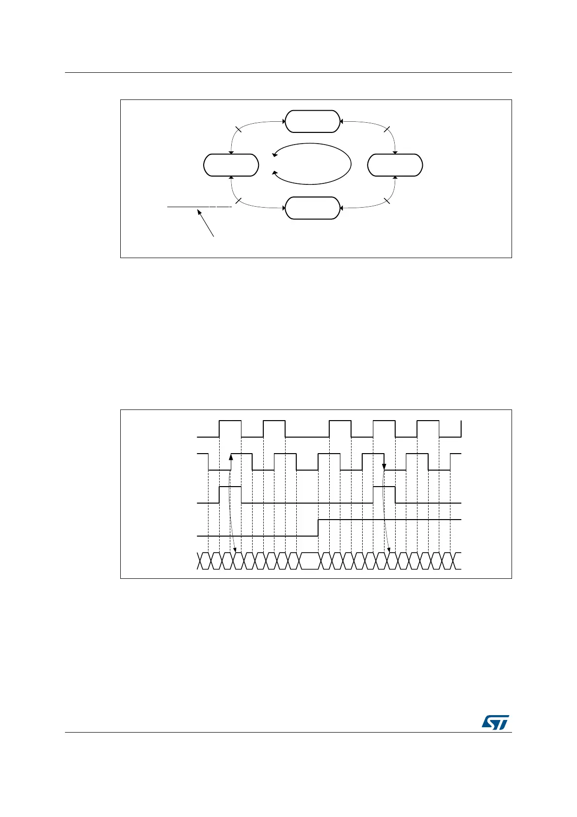
Figure 413. Index generation for IPOS[1:0] = 11
The Figure 414 below presents waveforms and corresponding values for IPOS[1:0] = 11. It
shows that the instant at which the counter value is forced is automatically adjusted
depending on the counting direction:
• Counter set to 0 when encoder state is '11' (ChA=1, ChB=1), when up-counting
(DIR bit = 0).
• Counter set to TIMx_ARR when exiting the '11' state, when down-counting
(DIR bit = 1).
An interrupt can be issued upon index detection event.
The arrows are indicating on which transition is the index event interrupt generated.
Figure 414. Counter reading with index gated on channel A (IPOS[1:0] = 11)
The Figure 415 below presents waveforms and corresponding values for the ungated mode.
The arrows are indicating on which transition is the index event generated.
MSv45767V1
AB = 00
State 1
AB = 01
State 2
AB = 10
State 4
AB = 11
State 3
Rotor angle = 0°
Rotor angle = 90°
Rotor angle = 180°
Rotor angle = 270°
Up-counting
Down-counting
The index event is always generated here
MSv45768V1
Channel A
Channel B
DIR bit
Index
Counter 5 6 7 0 1 2 3 4 5 6 5 4 3 2 1 0 7 6 5 4 3 2 1
 Loading...


