RM0440 Rev 4 285/2126
RM0440 Reset and clock control (RCC)
338
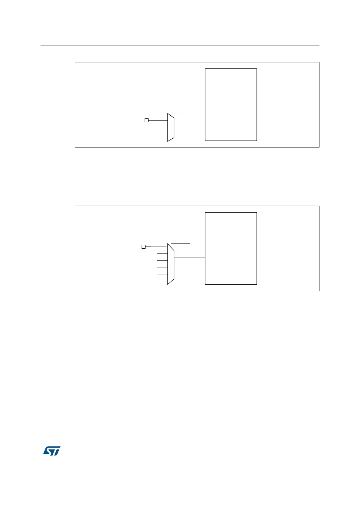
Figure 19. Frequency measurement with TIM15 in capture mode
The input capture channel of the Timer 15 can be a GPIO line or an internal clock of the
MCU. The possibilities are the following ones:
• TIM15 Channel1 is connected to the GPIO. Refer to the alternate function mapping in
the device datasheets.
• TIM15 Channel1 is connected to the LSE.
Figure 20. Frequency measurement with TIM16 in capture mode
The input capture channel of the Timer 16 can be a GPIO line or an internal clock of the
MCU.
The possibilities are the following ones:
• TIM16 Channel1 is connected to the GPIO. Refer to the alternate function mapping in
the device datasheets.
• TIM16 Channel1 is connected to the LSI clock.
• TIM16 Channel1 is connected to the LSE clock.
• TIM16 Channel1 is connected to the RTC wakeup interrupt signal. In this case the RTC
interrupt should be enabled.
• TIM16 Channel1 is connected to the HSE/32 clock.
• TIM16 Channel1 is connected to the MCO.
MS48963V1
TIM 15
TI1
TI1SEL in
TIM15_TISEL
GPIO
LSE
MSv45848V1
TIM 16
TI1
TI1SEL in
TIM16_TISEL
GPIO
LSE
LSI
RTC wakeup interrupt
HSE/32
MCO
 Loading...


