High-resolution timer (HRTIM) RM0440
894/2126 RM0440 Rev 4
The blanking signal comes from several sources:
• the timer itself: the blanking lasts from the counter reset to the compare match
(EExFLTR[3:0] = 0001 to 0100 for compare 1 to compare 4). In up/down mode (UDM
bit set to 1), the counter reset event is defined as per the ROM[1:0] bit setting.
• from other timing units (EExFLTR[3:0] = 0101 to 1100): the blanking lasts from the
selected timing unit counter reset to one of its compare match, or can be fully
programmed as a waveform on Tx2 output. In this case, events are masked as long as
the Tx2 signal is inactive (it is not necessary to have the output enabled, the signal is
taken prior to the output stage).
The EEXFLTR[3:0] configurations from 0101 to 1100 are referred to as TIMFLTR1 to
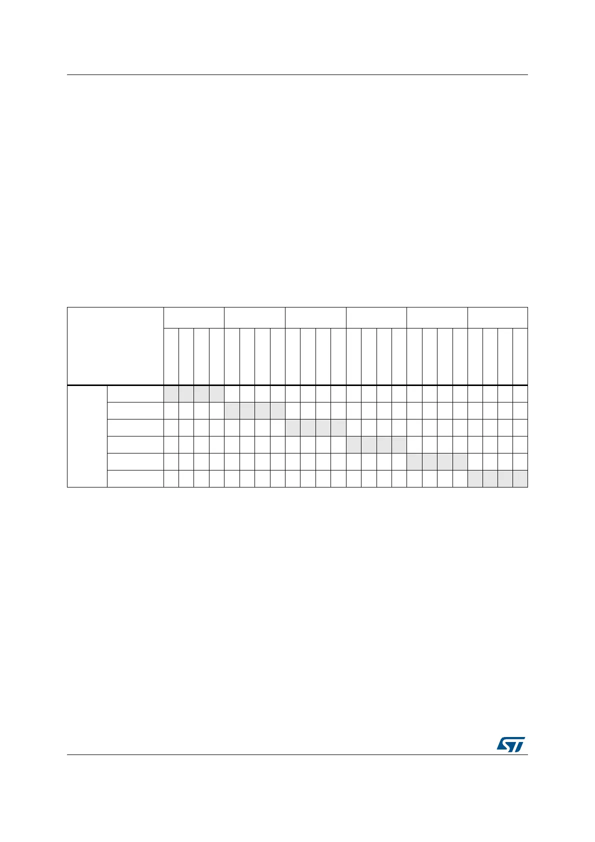
TIMFLTR8 in the bit description, and differ from one timing unit to the other. Table 224 gives
the 8 available options per timer: CMPx refers to blanking from counter reset to compare
match, Tx2 refers to the timing unit TIMx output 2 waveform defined with HRTIM_SETx2
and HRTIM_RSTx2 registers. For instance, timer B (TIMFLTR6) is timer C output 2
waveform.
Figure 221 and Figure 222 give an example of external event blanking for all edge and level
sensitivities, in regular and postponed modes.
Table 224. Filtering signals mapping per timer
Source
Timer A Timer B Timer C Timer D Timer E Timer F
CMP1
CMP2
CMP4
TA2
CMP1
CMP2
CMP4
TB2
CMP1
CMP2
CMP4
TC2
CMP1
CMP2
CMP4
TD2
CMP1
CMP2
CMP4
TE2
CMP1
CMP2
CMP4
TF2
Destination
Timer A - - - -1-234-5-7- - - -8--6---
Timer B 1 - 2 3
- - - -45-- -7--8- - --6--
Timer C - 1 - - 2 - 3 -
- - - -5-67- -8-4---
Timer D 1 - - - - 2 - - 3 4 - 5
- - - -6-7- --8-
Timer E -1- -2-- -3- - -6-78
- - - ---45
Timer F --1- -2-- - -3- -45-6-78
- - - -