RM0440 Rev 4 1407/2126
RM0440 General-purpose timers (TIM15/TIM16/TIM17)
1445
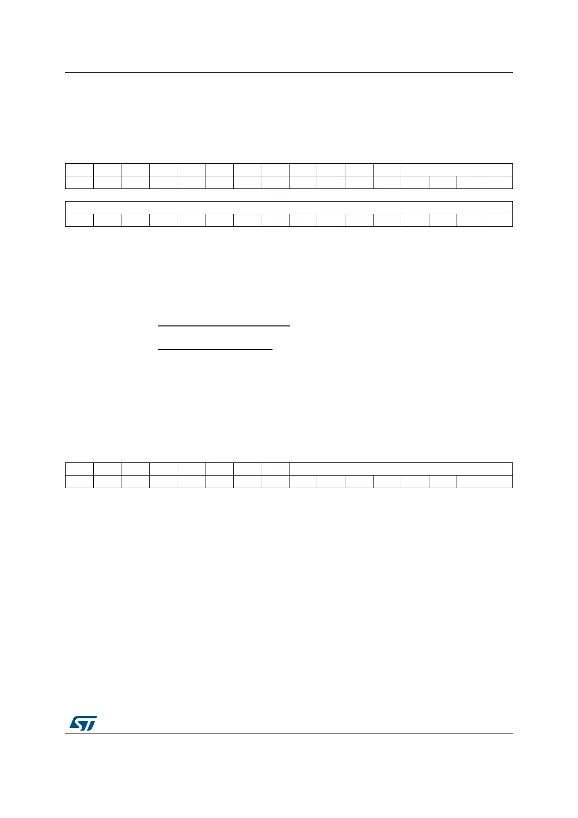
30.7.12 TIM15 auto-reload register (TIM15_ARR)
Address offset: 0x2C
Reset value: 0x0000 FFFF
30.7.13 TIM15 repetition counter register (TIM15_RCR)
Address offset: 0x30
Reset value: 0x0000
31 30 29 28 27 26 25 24 23 22 21 20 19 18 17 16
Res. Res. Res. Res. Res. Res. Res. Res. Res. Res. Res. Res. ARR[19:16]
rw rw rw rw
1514131211109876543210
ARR[15:0]
rw rw rw rw rw rw rw rw rw rw rw rw rw rw rw rw
Bits 31:20 Reserved, must be kept at reset value.
Bits 19:0 ARR[19:0]: Auto-reload value
ARR is the value to be loaded in the actual auto-reload register.
Refer to the Section 30.4.3: Time-base unit on page 1351 for more details about ARR
update and behavior.
The counter is blocked while the auto-reload value is null.
Non-dithering mode (DITHEN = 0)
The register holds the auto-reload value in ARR[15:0]. The ARR[19:16] bits are reset.
Dithering mode (DITHEN = 1)
The register holds the integer part in ARR[19:4]. The ARR[3:0] bitfield contains the dithered
part.
1514131211109876543210
Res. Res. Res. Res. Res. Res. Res. Res. REP[7:0]
rw rw rw rw rw rw rw rw
Bits 15:8 Reserved, must be kept at reset value.
Bits 7:0 REP[7:0]: Repetition counter reload value
This bitfield defines the update rate of the compare registers (i.e. periodic transfers from
preload to active registers) when preload registers are enable. It also defines the update
interrupt generation rate, if this interrupt is enable.
When the repetition down-counter reaches zero, an update event is generated and it
restarts counting from REP value. As the reptition counter is reloaded with REP value only
at the repetition update event UEV, any write to the TIM15_RCR register is not taken in
account until the next repetition update event.
It means in PWM mode (REP+1) corresponds to the number of PWM periods in edge-
aligned mode:
• the number of PWM periods in edge-aligned mode
• the number of half PWM period in center-aligned mode
 Loading...


