Universal synchronous/asynchronous receiver transmitter (USART/UART) RM0440
1670/2126 RM0440 Rev 4
37.7.10 USART interrupt and status register [alternate] (USART_ISR)
Address offset: 0x1C
Reset value: 0x0000 00C0
The same register can be used in FIFO mode enabled (previous section) and FIFO mode
disabled (this section).
FIFO mode disabled
Bit 2 NE: Noise detection flag
This bit is set by hardware when noise is detected on a received frame. It is cleared by
software, writing 1 to the NECF bit in the USART_ICR register.
0: No noise is detected
1: Noise is detected
Note: This bit does not generate an interrupt as it appears at the same time as the RXFNE bit
which itself generates an interrupt. An interrupt is generated when the NE flag is set
during multi buffer communication if the EIE bit is set.
When the line is noise-free, the NE flag can be disabled by programming the ONEBIT
bit to 1 to increase the USART tolerance to deviations (Refer to Section 37.5.8:
Tolerance of the USART receiver to clock deviation on page 1612).
This error is associated with the character in the USART_RDR.
Bit 1 FE: Framing error
This bit is set by hardware when a de-synchronization, excessive noise or a break character
is detected. It is cleared by software, writing 1 to the FECF bit in the USART_ICR register.
When transmitting data in Smartcard mode, this bit is set when the maximum number of
transmit attempts is reached without success (the card NACKs the data frame).
An interrupt is generated if EIE = 1 in the USART_CR1 register.
0: No Framing error is detected
1: Framing error or break character is detected
Note: This error is associated with the character in the USART_RDR.
Bit 0 PE: Parity error
This bit is set by hardware when a parity error occurs in receiver mode. It is cleared by
software, writing 1 to the PECF in the USART_ICR register.
An interrupt is generated if PEIE = 1 in the USART_CR1 register.
0: No parity error
1: Parity error
Note: This error is associated with the character in the USART_RDR.
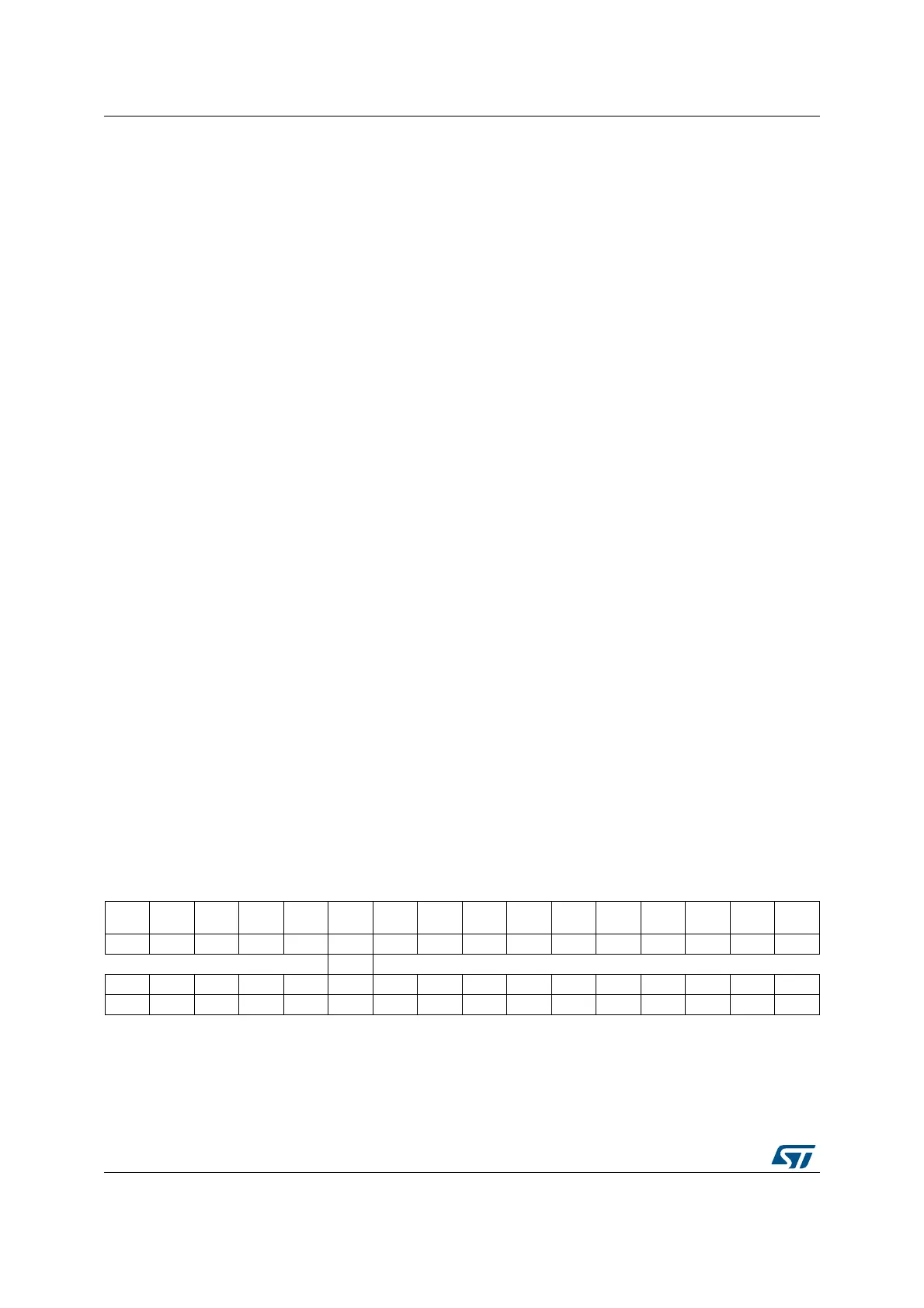
31 30 29 28 27 26 25 24 23 22 21 20 19 18 17 16
Res. Res. Res. Res. Res. Res. TCBGT Res. Res.
RE
ACK
TE
ACK
WUF RWU SBKF CMF BUSY
r rrrrrrr
1514131211109876543210
ABRF ABRE UDR EOBF RTOF CTS CTSIF LBDF TXE TC RXNE IDLE ORE NE FE PE
rrrrrrrrrrrrrrrr
 Loading...


