RM0440 Rev 4 607/2126
RM0440 Analog-to-digital converters (ADC)
724
Clock ratio constraint between ADC clock and AHB clock
There are generally no constraints to be respected for the ratio between the ADC clock and
the AHB clock except if some injected channels are programmed. In this case, it is
mandatory to respect the following ratio:
• F
adc_hclk
≥ F
ADC
/ 4 if the resolution of all channels are 12-bit or 10-bit
• F
adc_hclk
≥ F
ADC
/ 3 if there are some channels with resolutions equal to 8-bit (and none
with lower resolution)
• F
adc_hclk
≥ F
ADC
/ 2 if there are some channels with resolutions equal to 6-bit
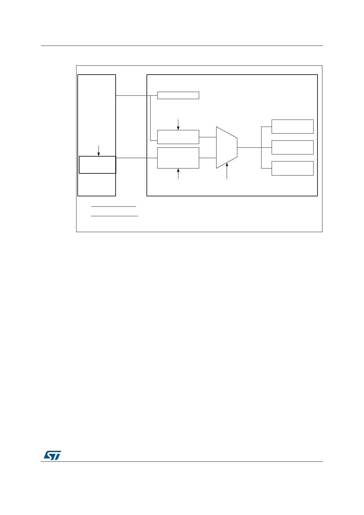
Figure 83. ADC clock scheme
MSv46144V2
Others
00
RCC
(Reset and
clock
controller)
(ADC1, ADC2) or (ADC3, ADC4, ADC5)
AHB interface
Analog ADC1 or 3
(master)
Analog ADC2 or 4
(slave)
Analog ADC5
(single)
/1 or /2 or /4
/1, 2, 4, 6, 8, 10,
12, 16, 32, 64,
128, 256
Bits PREC[3:0]
of ADCx_CCR
Bits CKMODE[1:0]
of ADCx_CCR
adc_hclk
Bits CKMODE[1:0]
of ADCx_CCR
adc_ker_ck
(1)
(1)
Synchronous clock sources
No jitter from trimer to conversion start
ADC12SEL[1:0]
or
ADC345SEL[1:0]
- System clock
- PLL ‘P’ output
(1)
(2)
(2)
Asynchronous clock sources
Better ADC frequency tuning independently from system and AHB clock
 Loading...


