Date printed: 22.07.08
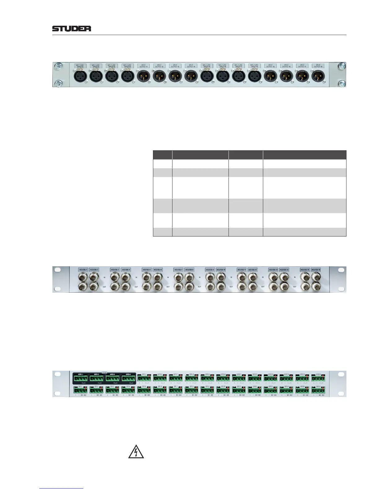
XLR Break-Out Box
This box is implemented as a congurable, modular system. The empty box
(1.949.580) can be equipped with different options for the left and right part.
The picture above shows a break-out box equipped with two options no. 3
for microphone inputs (2 × 4 XLR 3f) and the corresponding split outputs
(2 x 4 XLR 3m). On the rear of the box two 25-pin D-type sockets (f) are
provided for connection to the card(s) . For matching cables please refer to
the table at the end of this chapter.
Available Options:
Option Description Order no. Remarks
1
8 × XLR f to 1 × DB25 f 1.949.581 for 1 × Line input
2
8 × XLR m to 1 × DB25 f 1.949.582 for 1 × Line output
3
4 × XLR f / 4 × XLR m
to 1 × DB25 f
1.949.583
for 1 × Mic input/Split output
or 1 × Mic Insert send/return
or 1 × AES/EBU input/output
4
8 × XLR f to 2 × DB25 f 1.949.584
for 2 × Mic input
or 2 × AES/EBU input
5
4 × XLR f to 1 × DB25 f,
4 × blank cover
1.949.585
for 1 × Mic input
or 1 × AES/EBU input
6
8 × blank cover 8 × 31.03.0111
All XLR connectors can be custom-labeled with an inlay label.
AES/EBU on BNC Break-Out Box
(order no. 1.949.586)
This 19”/1 U box allows converting AES/EBU signals from balanced to unbal-
anced on BNC connectors and vice-versa. Each connector pair (in and out)
can be custom-labeled with an inlay label. On the rear of the box four 25-pin
D-type sockets (f) are provided for connection to the AES/EBU cards. For
matching cables please refer to the table at the end of this chapter.
Maximum cable lengths are 10 m for the D-type cables, and 100 m for the
BNC cables.
GPIO Break-Out Box
(order no. 1.949.588)
For easier wiring of single GPI and/or GPO signals, this break-out box can
be used. 16 GPI signals and 12 of the 16 GPO signals of a GPIO card with
relay outputs (1.949.436) are wired to single, 4-pin Combicon terminals (see
below), providing the relay contacts or opto-coupler inputs, as well as GND
and a short circuit-proof 5 V
DC
supply.
If voltages exceeding 50 V (AC or DC) are switched, the break-out box must
be placed within a closed rack in order to avoid shock hazards by touching
the contacts!