Four of the 16 GPO signals (GPO 1...4, marked in black on the front panel) are
connected to solid-state relays whose power terminals are wired to the Com-
bicon terminals. These power contacts can switch AC loads from 24...240 V
with a maximum total current of 5 A over all 4 relays.
For safety reasons, these four terminals have no additional GND and 5 V
supply. All remaining low-voltage terminals (GPI 1...16, GPO 5...16) are
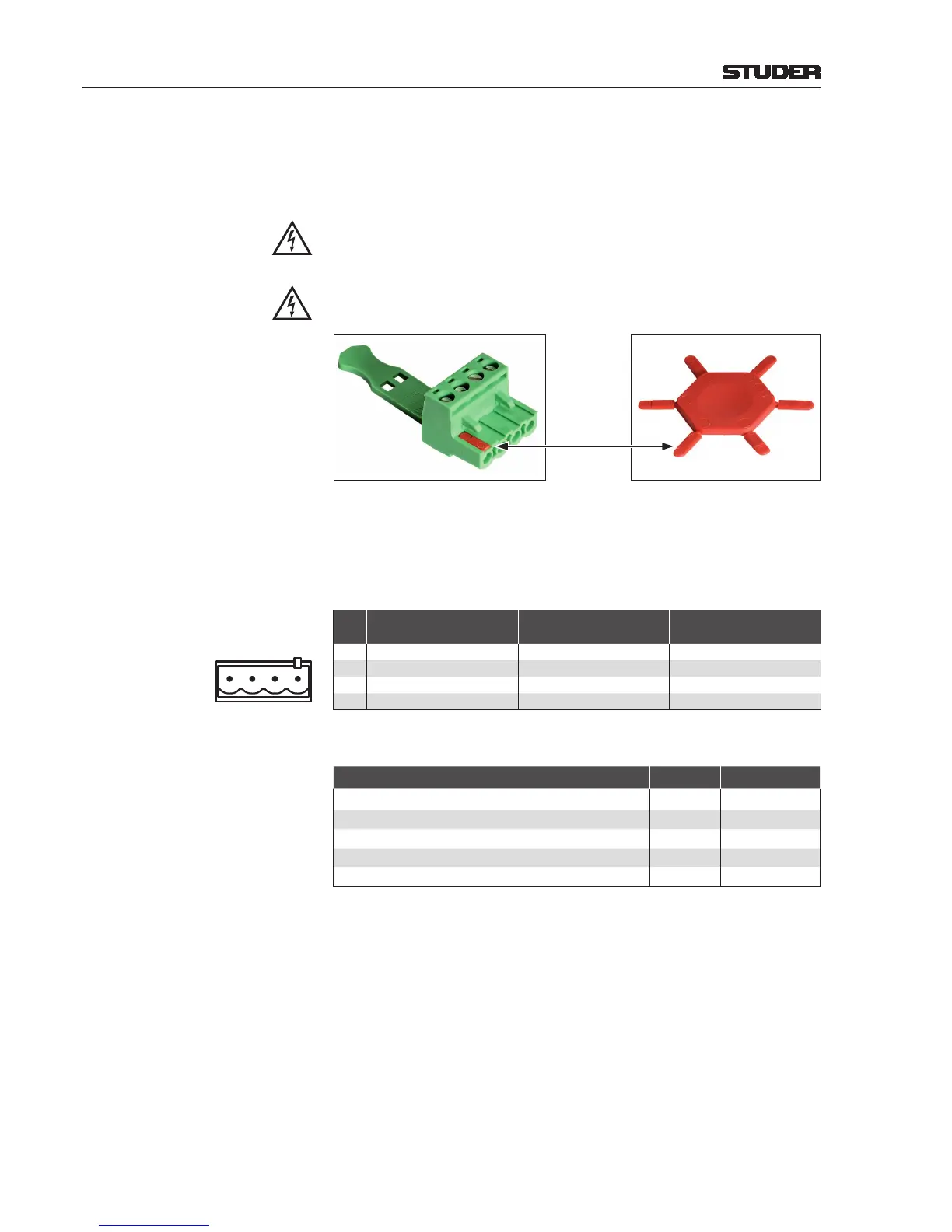
coded on pin #4 in order to prevent high-voltage connectors being inserted
by mistake.
The high-voltage connectors must be coded, as shown below; six coding
elements (order no. 54.25.1100) are included with the break-out box.
Eight 4-pin Combicon connectors with screw terminals (54.25.1104) are
included with the break-out box. If more connectors are required, please order
separately. On the rear of the box two 37-pin D-type sockets (f) are provided
for connection to the GPIO card. For matching cables please refer to the table
below.
Pin Assignment
Pin
GPO 1...4 (Outputs)
(upper row, *coded)
GPO 5...16 (Outputs)
(opper row, uncoded)
GPI 1...16 (Inputs)
(lower row, uncoded)
1 n.c. +5 V +5 V
2 n.c. GND GND
3 Power Relay, Contact 1 GPO Relay, Contact 1 Optocoupler Input 1
4 Power Relay, Contact 2 GPO Relay, Contact 2 Optocoupler Input 2
Cables for Break-Out Boxes
Description Length [m] Order no.
DB25 and DB37 Cables
DB25 m-m 1:1 cable, 8 × shielded 0.45 89.20.1161
DB25 m-m 1:1 cable, 8 × shielded 0.9 89.20.1174
DB25 m-m 1:1 cable, 8 × shielded 1.5 89.20.1170
DB37 m-m 1:1 cable 0.9 89.20.1178