22 Hardware
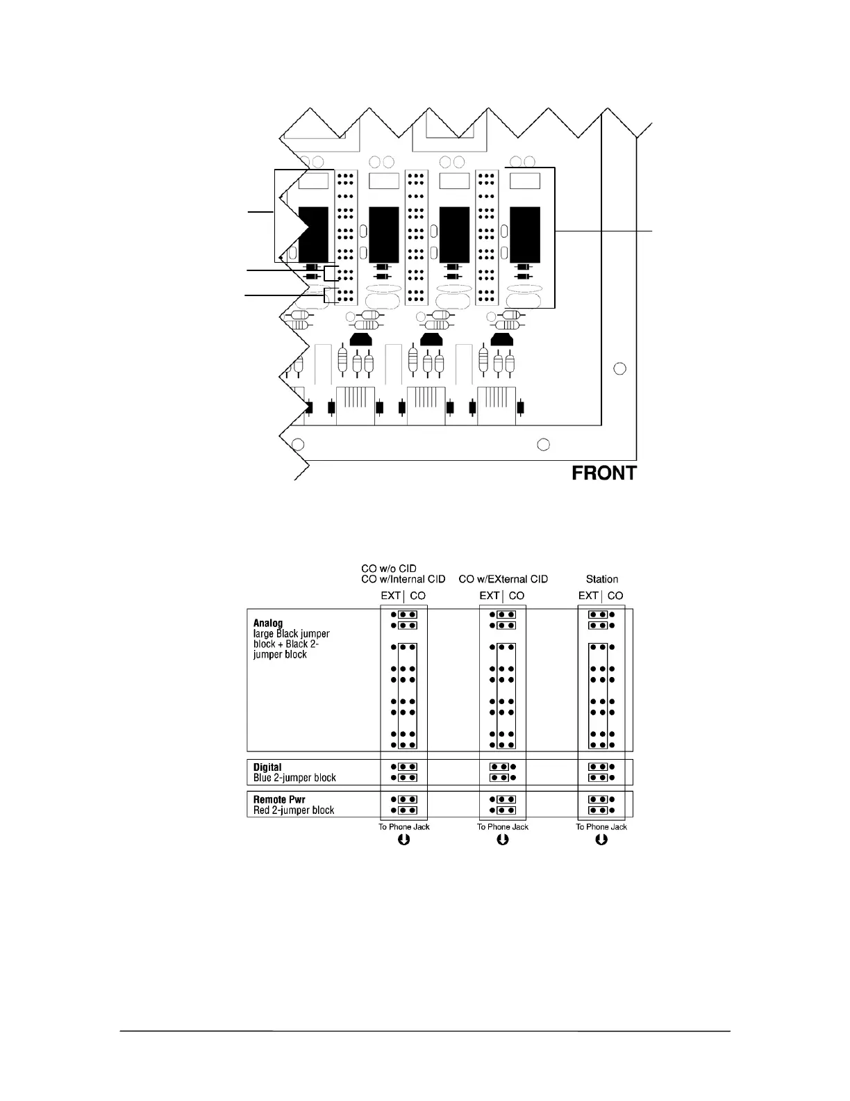
4. Set the jumpers for Port 1 based on the diagram below. Move all jumpers to the left side for a
station. Move all Analog (black) and Remote Power (red) jumpers to the right side for CO
ports, and set the digital (blue) jumpers based on having Internal Caller ID or External Caller
ID.
Jumper Settings
5. Repeat Steps 3 and 4 to set the jumpers for Ports 2–8.
6. When finished, replace the panel on the PEU.
7. Repeat Steps 1-6 for additional PEUs.
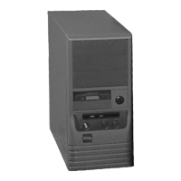
Port 1 jumper settings
Analog (black)
Digital (blue)
Remote Power (red)
Jumpers inside
the PEU