36 Hardware
Set to Ports SW1 SW2 SW3 SW4
1-32 ON ON ON OFF
33-64 OFF ON ON OFF
65-96 ON OFF ON OFF
97-128 OFF OFF ON OFF
129-160 ON ON OFF OFF
161-192 OFF ON OFF OFF
Note Each Host Adapter Card must be configured for the range of ports it will support. Do not
configure two Host Adapter Cards for the same range of ports, or the system will not work.
2. Disconnect the CO lines from the PEU, and then turn off the system and unplug it. Disconnect
the Host Adapter Cable. Remove the TVS cover, and then lay the TVS on its side with the front
facing forward.
3. Locate an available ISA slot, and then remove its slot cover from the back of the TVS case.
4. Insert the Host Adapter Card into the selected ISA slot, and then secure it with the screw from
the slot cover.
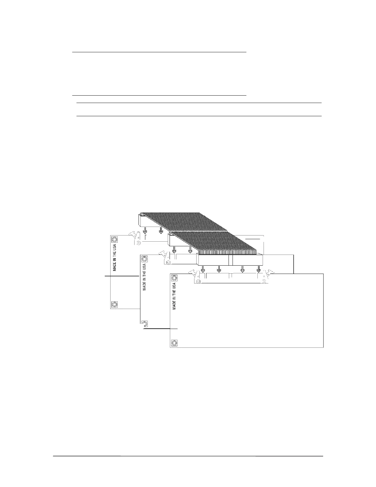
5. Connect the new Host Adapter Card to the PCM Bus connector cable already attached to the
first Host Adapter Card and the Switch Card.
PCM Bus ribbon
connection
6. Replace the TVS cover, plug in the system, and then turn the power on. Reconnect the CO lines
to the PEU.
After installing a Host Adapter Card, you can connect additional PEUs to your Telecor VS1 phone
system. For more information, see “Installing Additional PEUs,” page 28.
PCM Bus connector cable
Original Host
dapter Card
New Host
dapter Card