TOMATECH AUTOMATION
corresponding to four kinds of machining path as Fig. 3-46.
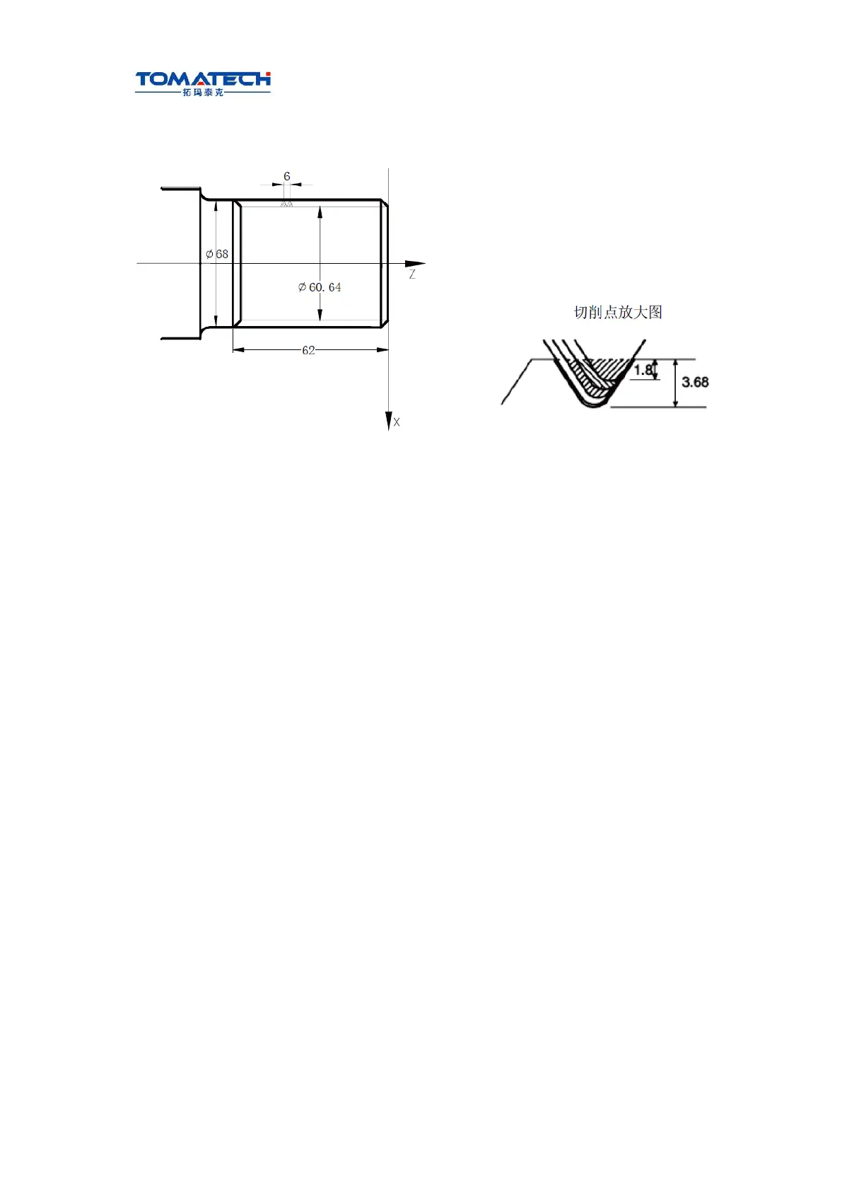
Example: Fig. 3-49, thread M68×6.
Fig.3-49
Program:
O0013;
G50 X100 Z50 M3 S300; (Set workpiece coordinate system, start spindle
and specify spindle speed)
G00 X80 Z10; (Rapid traverse to starting point of machining)
G76 P020560 Q150 R0.1; (Finishing 2 times, chamfering width 0.5mm, tool
angle 60°, min. cutting depth 0.15, finishing allowance 0.1)
G76 X60.64 Z-62 P3680 Q1800 F6; (Tooth height 3.68, the first cutting depth 1.8)
G00 X100 Z50 ; (Return to starting point of program)
M30; (End of program)
3.22 Constant Surface Speed Control G96, Constant Rotational
Speed Control G97
The detailed is referred to Section 2.2.3.
ming
3.23 Feedrate per Minute G98, Feedrate per Rev G99
Command format: G98 F_; (its range is referred to Section 1.6.5, the leading zero can be
omitted, feed rate per minute is specified, mm/min)
Command function: cutting feed rate is specified as mm/min, G98 is the modal G
command.G98 cannot be input if the current command is G98 modal.
Command format: G99 F_; (its range is referred to Section 1.6.5, the leading zero can be
omitted)
Command function: Cutting feed rate is specified as mm/min, G99 is the modal G
command.G99 input may be omitted if current state is G99. The actual cutting
feedrate is gotten by multiplying the F command value (mm/r) to the current spindle
speed(r/min). If the spindle speed varies, the actual feedrate changes too. If the spindle