TOMATECH AUTOMATION
Fig. 4-9 Tool nose center on starting point
4.1.3 Compensation value setting
Preset imaginary tool nose number and tool nose radius value for each tool before
executing tool nose radius compensation. Set the tool nose radius compensation value in
OFFSET window (as Fig. 4-1), R is tool nose radius compensation value and T is
imaginary tool nose number.
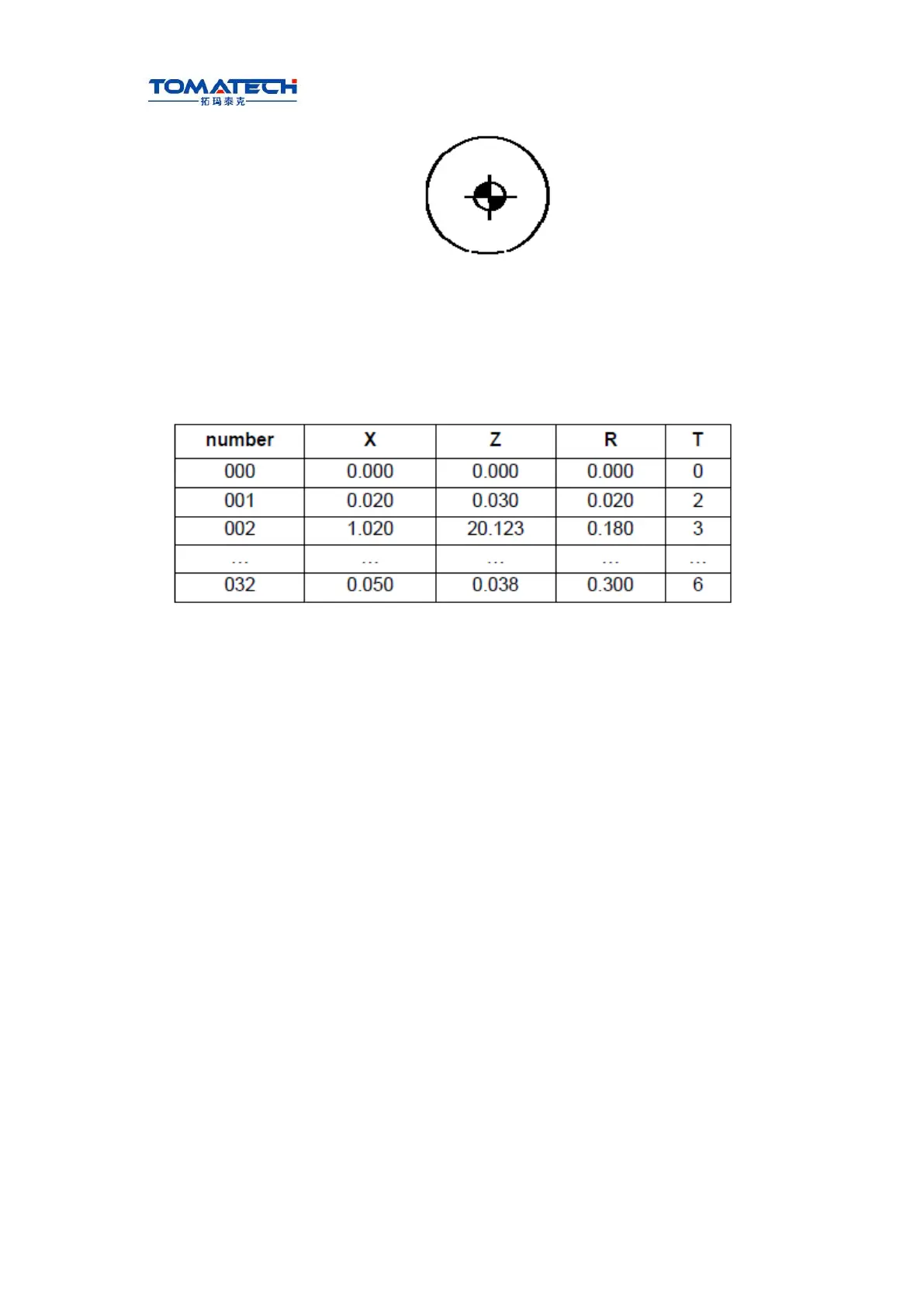
Table 4-1 CNC tool nose radius compensation value display window
Note: X tool offset value can be specified in diameter or radius, set by No.004 Bit4 ORC, offset
value is in radius when ORC=1 and is in diameter when ORC=0.
In toolsetting, the tool nose is also imaginary tool nose point of Tn (n=0~9) when taking
Tn(n=0~9) as imaginary tool nose. For the same tool, offset value from standard point to
tool nose radius center (imaginary tool nose is T3) is different with that of ones from
standard point to imaginary
tool nose(imaginary tool nose is T3) when T0 and T3 tool nose points are selected to
toolsetting in rear tool post coordinate system, taking tool post center as standard point. It
is easier to measure distances from the standard point to the tool nose radius center than
from the standard point to the imaginary tool nose, and so set the tool offset value by
measuring distance from the standard point to the imaginary tool nose
(tool nose direction of T3).