TOMATECH AUTOMATION
metric machine: 0.001 mm
inch machine: 0.0001 inch
When the setting is 100, the metric machine is 0.1mm and the inch machine is 0.01
inch.
Position parameters: No.34, No.35, No.37~No.40, No.45~No.48, No.102~No.104 and
all pitch error compensation parameter;
Note 1: When the minimal input increment unit and the minimal command unit are different, the
maximal error
is the half of minimal command unit. The error cannot be accumulated.
Note 2: The current system increment is IS-B in the above explanation.
Ⅰ Programming
CHAPTER 4
TOOL NOSE RADIUS COMPENSATION (G41, G42)
4.1 Application
4.1.1 Overview
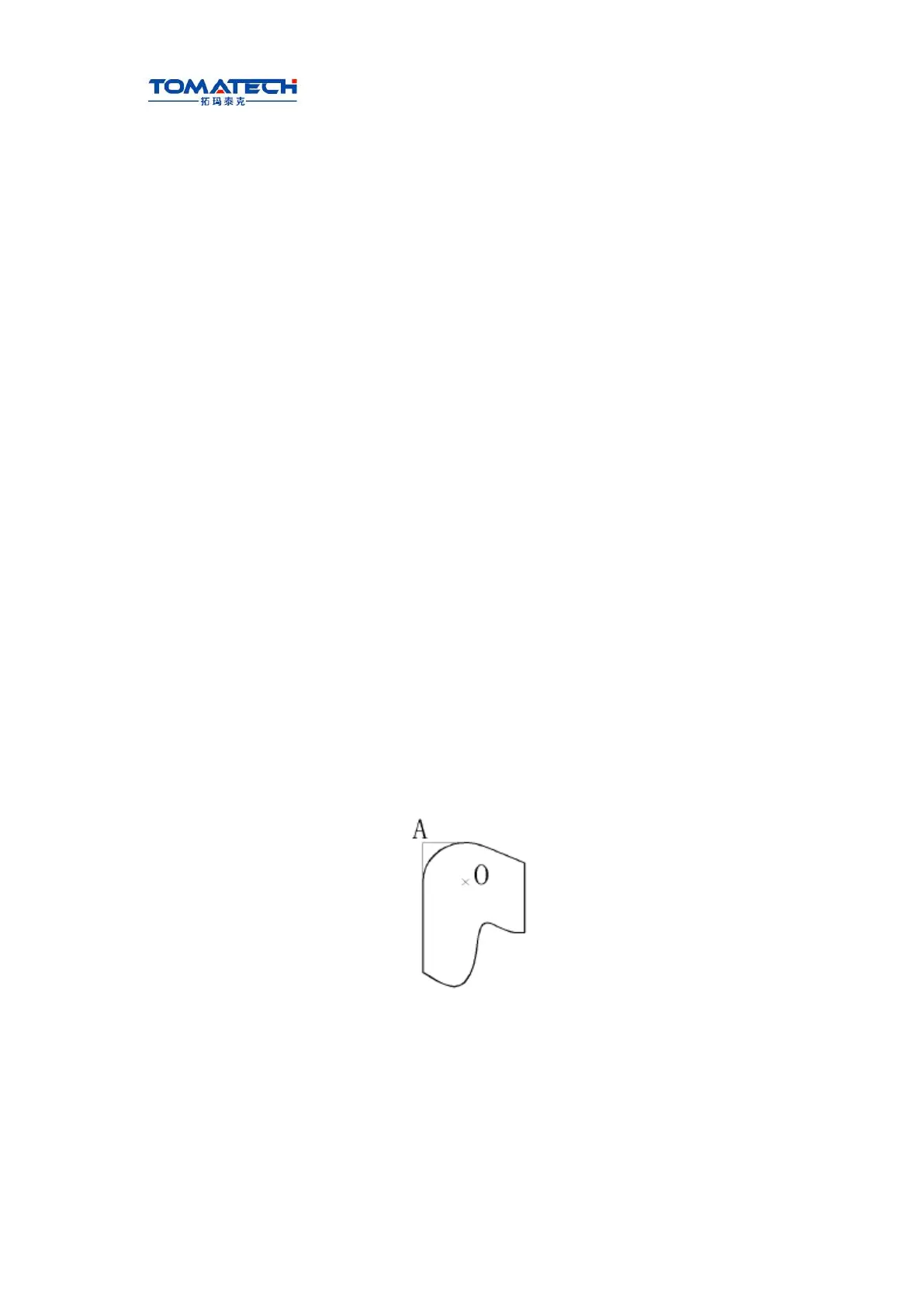
Part program is compiled generally for one point of tool according to a workpiece contour.
The point is generally regarded as the tool nose A point in an imaginary state (there is no
imaginary tool nose point in fact and the tool nose radius can be omitted when using the
imaginary tool nose point to program) or as the center point of tool nose arc ( as Fig. 4-1).
Its nose of turning tool is not the imaginary point but one arc owing to the processing and
other requirement in the practical machining.
There is an error between the actual cutting point and the desired cutting point, which will
cause the over- or under-cutting affecting the part precision. So a tool nose radius
compensation is needed in machining to improve the part precision.
Fig. 4-1 Tool