TOMATECH AUTOMATION
control function.
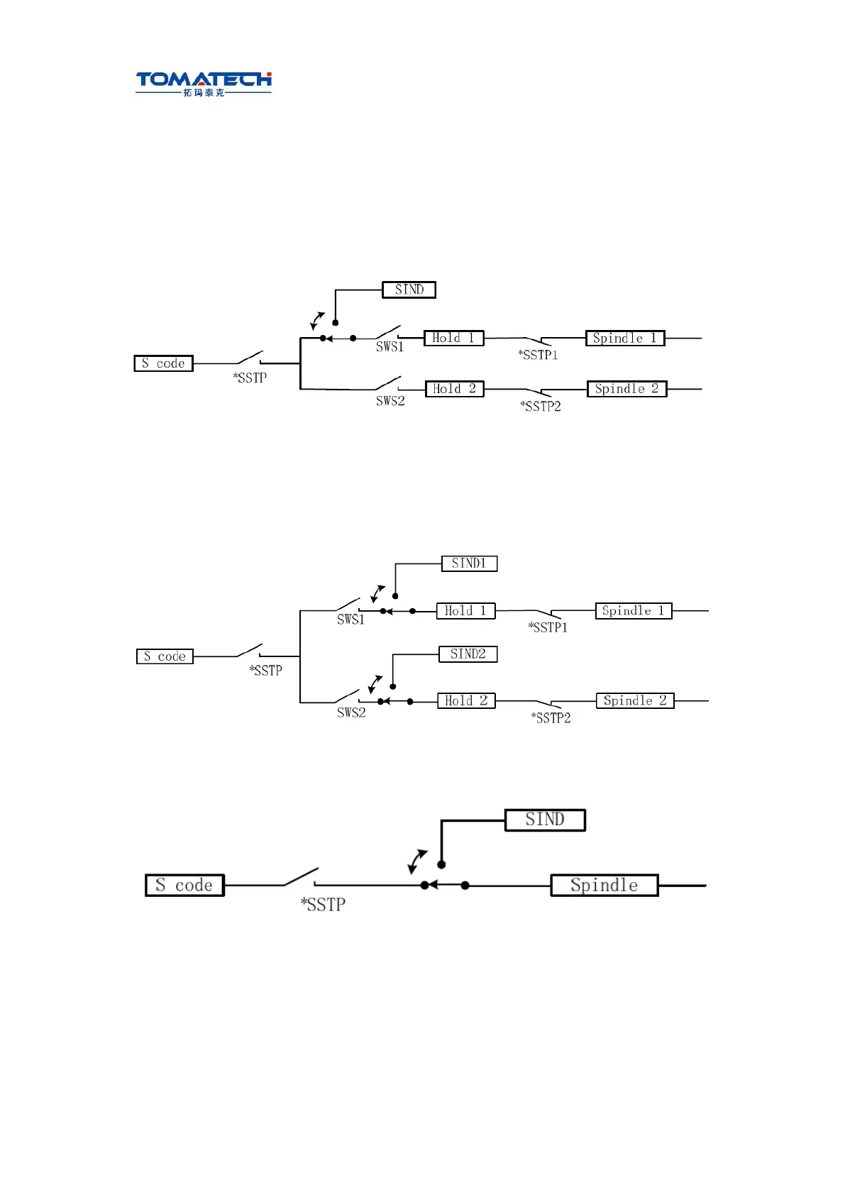
The spindle control has several methods which are set by MSI(№196#7)as follows:
� Multiple spindle control method A
When SWS1 signal selects the 1st spindle, SIND signal is used to determine that the
spindle analog voltage is controlled by PLC or CNC, R011 to R121 signals are used to set
the spindle analog voltage. These signals do not influence the 2nd spindle.
Multiple spindle control method A is shown below.
� Multiple spindle control method B
Each spindle has separate SIND signal.
When the spindle selection signal, the 1st spindle or the 2nd spindle SIND signal is set to 1,
SIND signals separately determine each spindle to be controlled by PLC or CNC.
Multiple spindle control method B is shown below.
Target tool number(01-32,the leading zero cannot be omitted)
� Multiple spindle control function being invalid
When the multiple spindle control is invalid, the control method is shown below.
2.2.6 Cs contour control funciton
Controlling a spindle speed is called as the spindle rotation control (the spindle rotates by
the speed command), and controlling the spindle position is called as the spindle contour
control (the spindle rotates by the movement command). The function of the spindle
contour control is that of Cs contour control. Being the servo feed axis, the spindle rotates
and orients by the position movement command, and executes the interpolation with other
feed axes to machine the contour curve.