2.7 Install the Keypad to a Control Panel or Another Device
48 YASKAWA ELECTRIC SIEP C710617 05F YASKAWA AC Drive GA700 Technical Manual
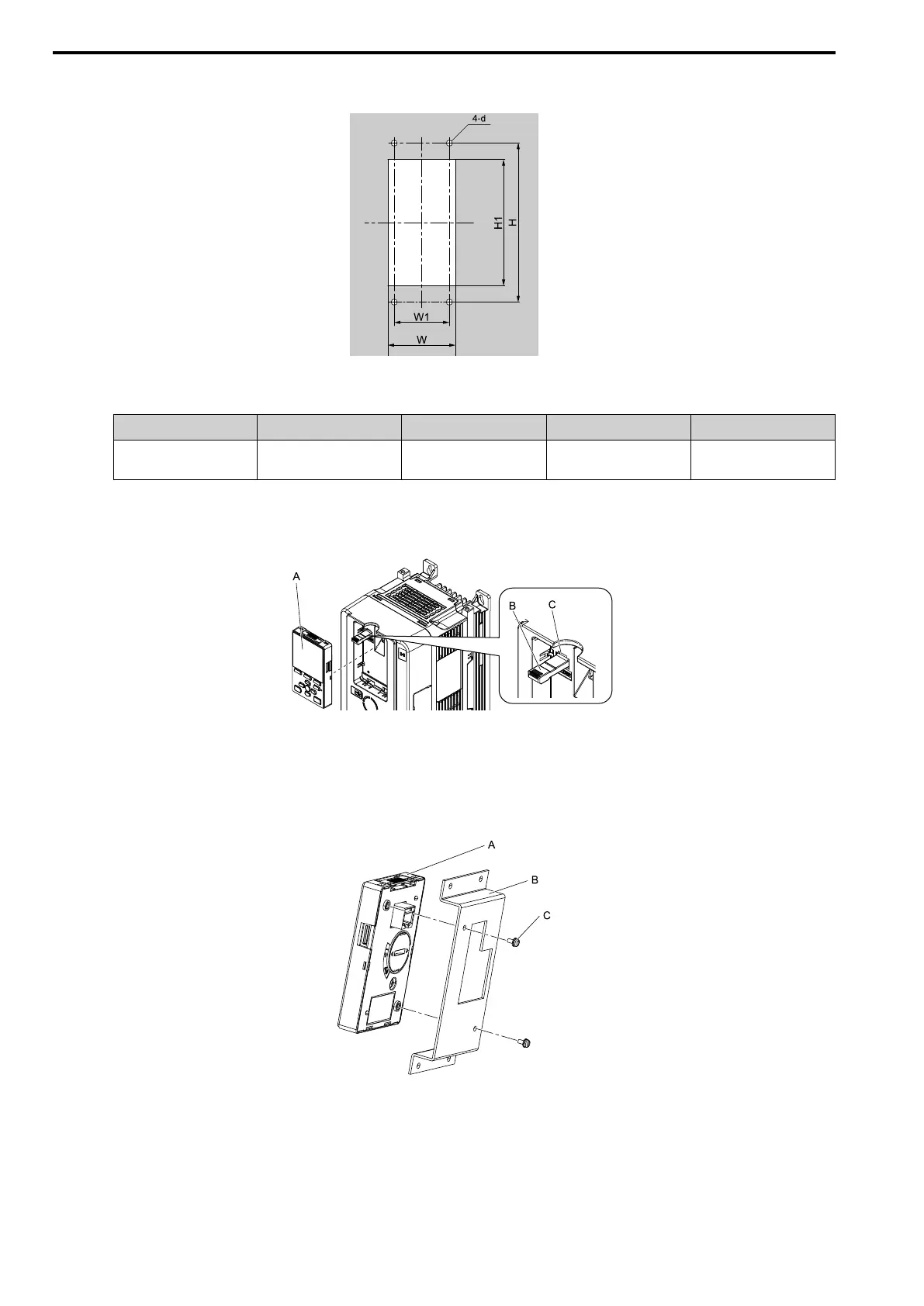
1. Use the panel cut-out dimensions in Figure 2.15 and Table 2.10 to cut an opening in the control panel for
the keypad.
Figure 2.15 Panel Cut-Out Dimensions to Attach Inside Control Panel
Table 2.10 Panel Cut-out Dimensions mm (in.)
W H W1 H1 d
64 + 0.5 (2.52 + 0.02) 130 (5.12) 45 (1.77) 105 + 0.5 (4.13 +
0.02)
4.8 (0.12)
2. Remove the keypad and put the keypad connector in the holder on the front cover.
Note:
Insert the end of the keypad connector that has the tab.
A - Keypad
B - Keypad connector
C - Holder
Figure 2.16 Remove the Keypad
3. Use the screws supplied with the mounting bracket, and attach the keypad to the mounting bracket.
Tighten the screws to a tightening torque of 0.49 to 0.73 N∙m (4.34 to 6.46 lb.∙in.).
A - Keypad
B - Mounting bracket A
C - M3 screws
Figure 2.17 Attach Keypad to Mounting Bracket