Mechanical & Electrical
Installation
2
2.12 Main Circuit Wiring
YASKAWA ELECTRIC SIEP C710617 05F YASKAWA AC Drive GA700 Technical Manual 87
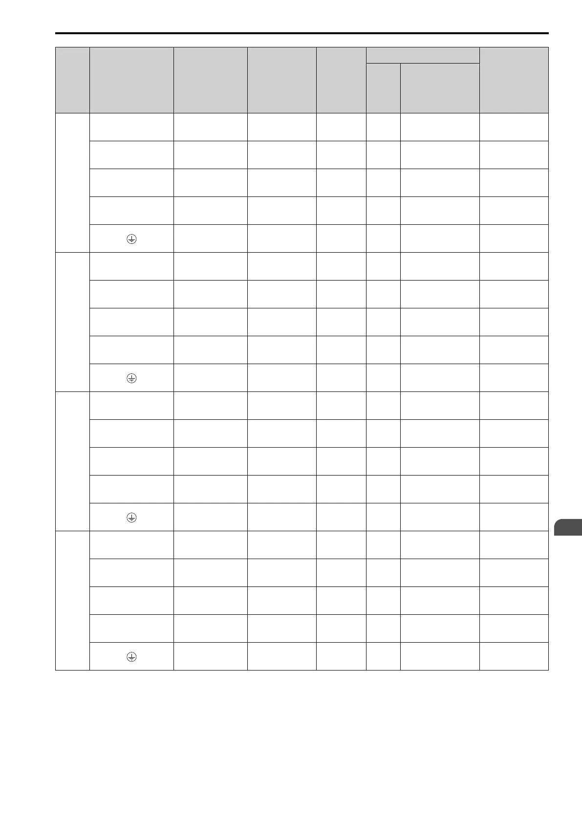
Model Terminals
Recommended
Gauge
mm
2
Applicable
Gauge
(IP20
Applicable
Gauge
*1
)
mm
2
Wire
Stripping
Length
*2
mm
Terminal Screw
Tightening
Torque
N∙m (lb.∙in.)
Size Shape
2257
R/L1, S/L2, T/L3 50 × 2P
25 - 95 × 2P
(70 - 95 × 2P)
- M10 Hex self-locking nut
20
(177)
U/T1, V/T2, W/T3 50 × 2P
25 - 95 × 2P
(70 - 95 × 2P)
- M10 Hex self-locking nut
20
(177)
-, +1 70 × 2P
35 - 120 × 2P
(120 × 2P)
- M10 Hex self-locking nut
20
(177)
+3 35 × 2P
25 - 70 × 2P
(70 × 2P)
- M10 Hex self-locking nut
20
(177)
95
95 - 240
(-)
- M10 Hex bolt (slotted)
18 - 23
(159 - 204)
2313
R/L1, S/L2, T/L3 70 × 2P
25 - 95 × 2P
(70 - 95 × 2P)
- M10 Hex self-locking nut
20
(177)
U/T1, V/T2, W/T3 70 × 2P
25 - 95 × 2P
(70 - 95 × 2P)
- M10 Hex self-locking nut
20
(177)
-, +1 95 × 2P
35 - 120 × 2P
(120 × 2P)
- M10 Hex self-locking nut
20
(177)
+3 50 × 2P
25 - 70 × 2P
(70 × 2P)
- M10 Hex self-locking nut
20
(177)
95
95 - 240
(-)
- M10 Hex bolt (slotted)
18 - 23
(159 - 204)
2360
R/L1, S/L2, T/L3 120 × 2P
70 - 150 × 2P
(150 × 2P)
- M12 Hex self-locking nut
35
(310)
U/T1, V/T2, W/T3 120 × 2P
70 - 150 × 2P
(150 × 2P)
- M12 Hex self-locking nut
35
(310)
-, +1 120 × 2P
95 - 185 × 2P
(185 × 2P)
- M12 Hex self-locking nut
35
(310)
+3 70 × 2P
50 - 95 × 2P
(-)
- M12 Hex self-locking nut
35
(310)
120
120 - 240
(-)
- M12 Hex bolt (slotted)
32 - 40
(283 - 354)
2415
R/L1, S/L2, T/L3 120 × 2P
70 - 150 × 2P
(150 × 2P)
- M12 Hex self-locking nut
35
(310)
U/T1, V/T2, W/T3 120 × 2P
70 - 150 × 2P
(150 × 2P)
- M12 Hex self-locking nut
35
(310)
-, +1 120 × 2P
95 - 185 × 2P
(185 × 2P)
- M12 Hex self-locking nut
35
(310)
+3 70 × 2P
50 - 95 × 2P
(-)
- M12 Hex self-locking nut
35
(310)
120
120 - 240
(-)
- M12 Hex bolt (slotted)
32 - 40
(283 - 354)
*1 For IP20 protection, use wires that are in the range of applicable gauges.
*2 Remove insulation from the ends of wires to expose the length of wire shown.
*3 For wire gauges more than 30 mm
2
, tighten to a tightening torque of 4.1 N∙m to 4.5 N∙m (36 lb.∙in. to 40 lb.∙in.).
*4 Install an RCM/RCD with this wire gauge to maintain compliance with IEC/EN 61800-5-1:2007.
*5 Terminals - and +1 have two screws. The Recommended Gauge is the wire gauge for one terminal.
*6 A junction terminal is necessary to connect a braking unit (CDBR-series) to terminals - and +3.