Mechanical & Electrical
Installation
2
2.12 Main Circuit Wiring
YASKAWA ELECTRIC SIEP C710617 05F YASKAWA AC Drive GA700 Technical Manual 95
WARNING! Electrical Shock Hazard. Make sure that the protective ground wire complies with technical standards and local
safety regulations. The leakage current of the drive will be more than 3.5 mA in drive models 2xxxB, 2xxxC, 4002B to 4371B,
4002C to 4371C (with EMC filter turned ON) and 4389 to 4675. The IEC/EN 61800-5-1:2007 standard specifies that you must
wire the power supply to automatically turn off when the protective ground wire disconnects. You can also connect a protective
ground wire that has a minimum cross-sectional area of 10mm
2
(copper wire) or 16 mm
2
(aluminum wire). Failure to obey these
standards can cause death or serious injury.
WARNING! Electrical Shock Hazard. Ground the neutral point on the power supply of drive models 2xxxB/C and 4xxxA/B/C to
comply with the EMC Directive before turning on the EMC filter or if there is high resistance grounding. If the EMC filter is
switched ON without the neutral point being grounded or if there is high resistance grounding, it can cause death or serious
injury.
WARNING! Electrical Shock Hazard. Use a ground wire that complies with technical standards on electrical equipment and use
the minimum length of ground wire. Incorrect equipment grounding can cause serious injury or death from dangerous electrical
potentials on the equipment chassis.
WARNING! Electrical Shock Hazard.
Correctly ground the ground terminals. Obey federal and local electrical wiring codes for correct grounding methods.
• 200 V class: ground to 100 Ω or less
• 400 V class: ground to 10 Ω or less
Failure to obey can cause death or serious injury from contacting ungrounded electrical equipment.
NOTICE: Do not share the ground wire with other devices, for example welding machines or large-current electrical equipment.
Incorrect equipment grounding can cause drive or equipment malfunction from electrical interference.
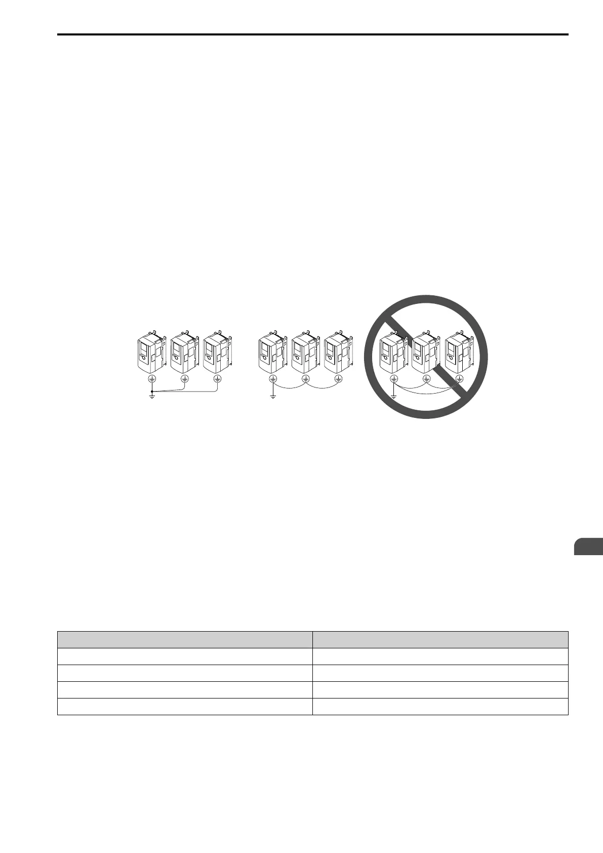
NOTICE: To use more than one drive, obey the instructions to ground all drives. Incorrect equipment grounding can cause
incorrect operation of drives and equipment.
Refer to Figure 2.83 when connecting more than one drive. Do not loop the grounding wire.
Figure 2.83 Wiring More than One Drive
■ Wiring the Main Circuit Terminal Block
WARNING! Electrical Shock Hazard. De-energize the drive and correctly ground the terminal board before you wire the main
circuit terminals. Failure to obey can cause death or serious injury.
■ Main Circuit Configuration
The figures in this section show the different schematics of the drive main circuit The connections change when
the drive capacity changes. The DC power supply for the main circuit also supplies power to the control circuit.
Note:
Drive models 2004A to 2415A and 4002A to 4675A do not have a built-in EMC filter.
WARNING! Fire Hazard. The braking resistor connection terminals are B1 and B2. Do not connect braking resistors to other
terminals. Incorrect wiring connections could cause the braking resistor to overheat. Failure to obey can cause death or serious
injury by fire and damage to the drive and braking circuit.
NOTICE: Do not use the negative DC bus terminal “-” as a ground terminal. This terminal is at high DC voltage potential.
Incorrect wiring connections could cause damage to the drive.
Model Figure
2004 to 2082, 4002 to 4044
Figure 2.84
2110 to 2138, 4060 to 4168
Figure 2.85
2169 to 2313, 4208 to 4250
Figure 2.86
2360 to 2415, 4296 to 4675
Figure 2.87
 Loading...


