149
Corrective Maintenance
Printhead Assembly
8/9/07 ZM400/ZM600 Maintenance Manual 14207L-001 A
3. See Figure 28 on page 147. Connect both printhead power and data cables to the printhead
connectors and carefully slide them into position. Ensure the cables are in their proper
channels and are not binding the printhead.
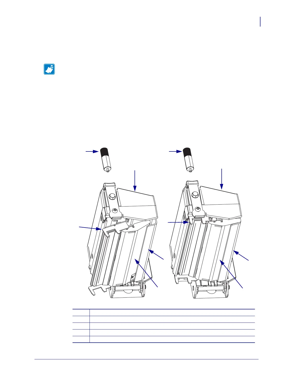
4. See Figure 29 and Figure 30. Tip the printhead fork assembly slightly and insert the
printhead ribbon guide into the print mechanism as shown.
5. See Figure 29 and Figure 30. Tip the printhead fork assembly up and into the print
mechanism ensuing that the two locating protrusions on either side of the print printhead
snap into the locating holes of the ribbon guide plate. Move the assembly back and forth to
be sure that it is engaged. There should be little movement.
Figure 30 • Install the Printhead Fork Assembly
Note • When mounting the printhead fork assembly onto the print mechanism, visually
inspect and ensure the cables are in their channels at the back of their carrier assembly,
power cable under data cable, and are not binding on the print mechanism.
1
Thumbscrew
2
Print mechanism
3
Printhead fork assembly
4
Ribbon guide plate
5
Printhead ribbon guide
1
1
2
2
3
3
4
5
4
5
 Loading...