165
Corrective Maintenance
Print Mechanism
8/9/07 ZM400/ZM600 Maintenance Manual 14207L-001 A
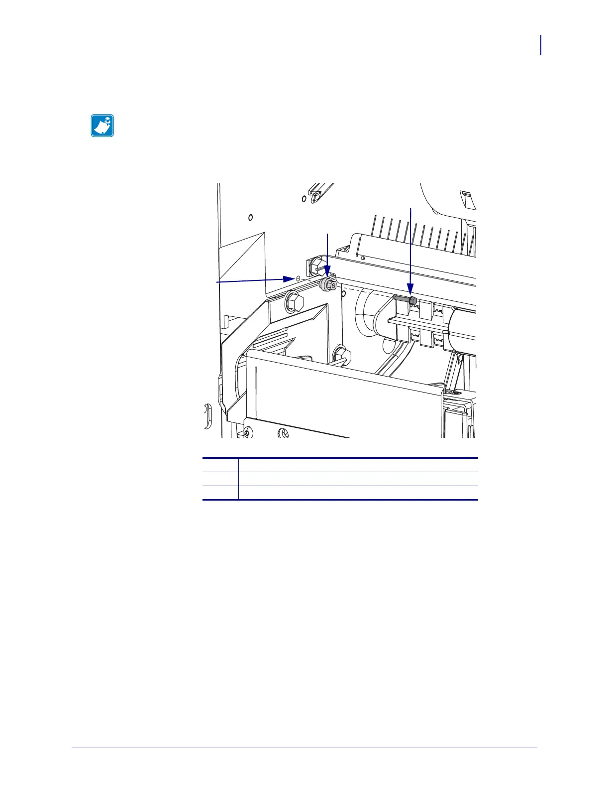
2. See Figure 44. Using the screw provided in the kit, install the print mechanism adjustment
cam on the printer main frame.
Figure 44 • Install the Adjustment Cam
3. See Figure 43. Insert the print mechanism gap pin gauges through the holes that are
provided in the front of the ribbon guide plate.
4. See Figure 41 on page 162. Slightly loosen the three print mechanism mounting screws.
5. See Figure 43. Place a 10 cm adjustable wrench on the print mechanism adjustment cam.
While turning the wrench counterclockwise, push in and pull out the inside gap pin gauge
until a small amount of friction can be felt.
6. After aligning the inside pin gauge, use a screwdriver and turn the adjustment screw on
top of the latch plate strike.
7. Push in and pull out the outside gap pin gauge until a small amount of friction can be felt.
Double check both pin gauges for equal amount of friction.
8. Tighten the latch plate strike screws.
9. Tighten the print mechanism mounting screws when equal pressure is obtained.
Note • The cam should be in contact with print mechanism. Just snug the cam in place.
1
Cam mounting hole
2
Cam
3
Mounting screw
1
2
3
 Loading...