EasyManuals Logo

Zebra ZM400 Series User Manual

Zebra ZM400 Series
470 pages
To Next Page IconTo Next Page
To Previous Page IconTo Previous Page
Page #166 background imageLoading...
Page #166 background image
Corrective Maintenance
Print Mechanism
166
14207L-001 A ZM400/ZM600 Maintenance Manual 8/9/07
10. Replace the strike plate cap.
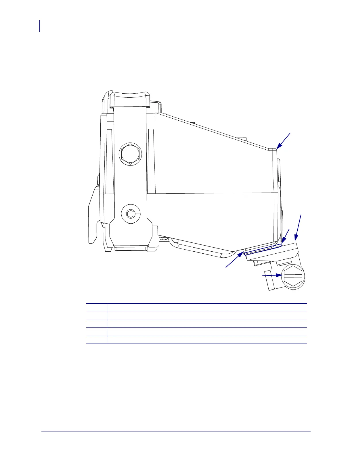
11. See Figure 45. Check the gap on the ribbon/printhead open sensor and adjust as necessary.
Figure 45 • Ribbon/Printhead Open Sensor
12. Use a 1.25 mm (0.050 in.) feeler gauge and check the distance between the ribbon/head
open sensor assembly and the ribbon guide plate.
If the distance is incorrect, loosen the mounting screw for the ribbon/head open sensor and
adjust for the proper distance. Once this distance is achieved, tighten the mounting screw.
1
Printhead housing
2
Gap, 1.25 mm (0.050 in.)
3
Ribbon/Printhead open sensor
4
Mounting screw
5
Ribbon guide plate
1
2
3
4
5

Table of Contents

Questions and Answers:

Question and Answer IconNeed help?

Do you have a question about the Zebra ZM400 Series and is the answer not in the manual?

Zebra ZM400 Series Specifications

General IconGeneral
Max Print Width4.09 inches (104 mm)
Max Print Speed10 inches per second (254 mm per second)
Print MethodThermal Transfer/Direct Thermal
Resolution203 dpi (8 dots/mm)
ConnectivityUSB 2.0, Serial RS-232, Parallel, Internal Ethernet (10/100), optional wireless
Media Width1"/25.4 mm to 4.5"/114 mm
Media Length0.25 to 39 inches (6 to 991 mm)
Media Thickness0.0023"/0.058 mm to 0.010"/0.25 mm
Ribbon Width1"/25.4 mm to 4.33"/110 mm
Ribbon Length1476 feet (450 m)
Supported Media TypesContinuous, die-cut, notch, black-mark
Operating Temperature40°F to 105°F (5°C to 40°C)
Storage Temperature-40°F to 140°F (-40°C to 60°C)

Related product manuals