Corrective Maintenance
Printhead Cables
182
14207L-001 A ZM400/ZM600 Maintenance Manual 8/9/07
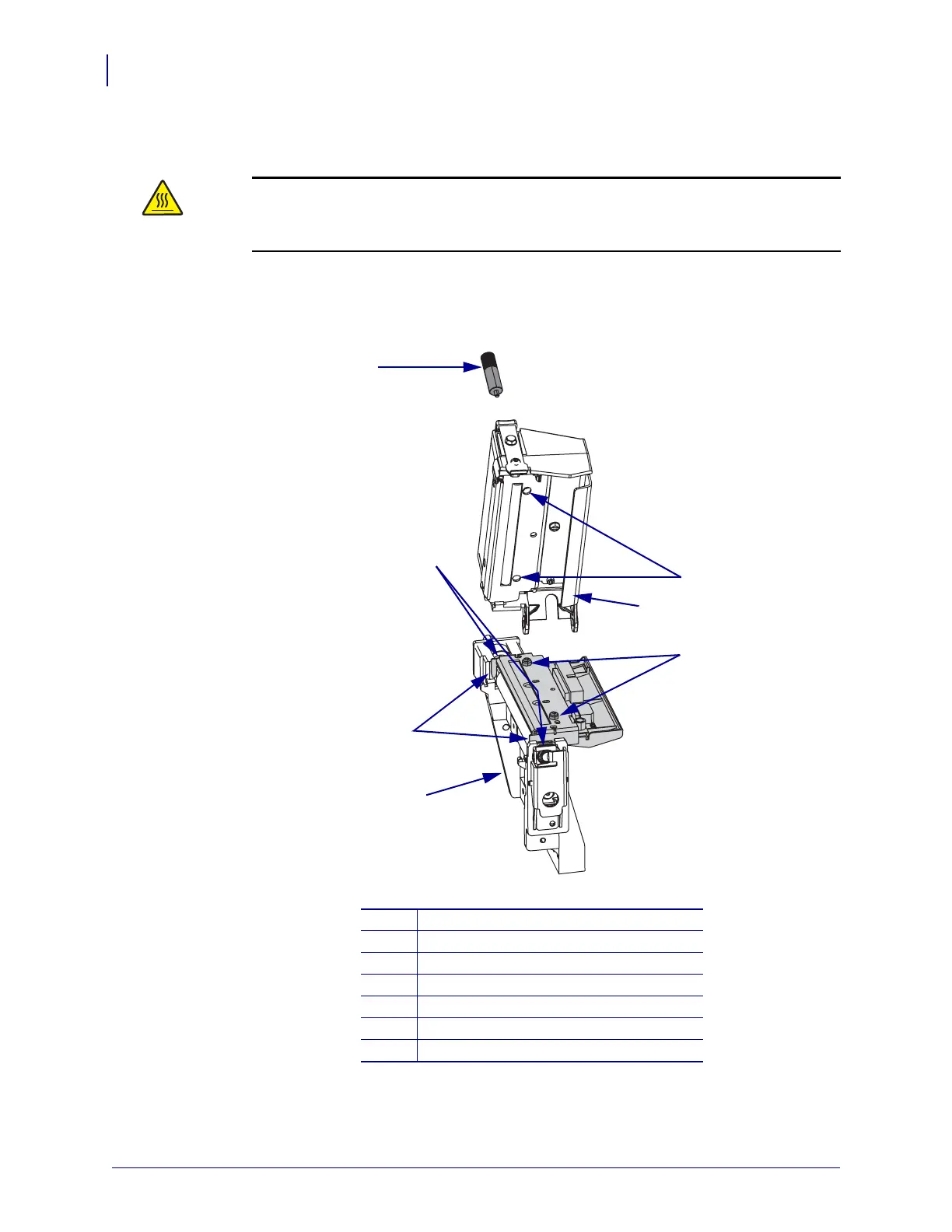
4. See Figure 60. Align the two forks with the bearings and set the printhead assembly onto
the platen housing.This is done for ease of connecting the printhead cables.
5.
Figure 60 • Align the Forks and Bearings
6. See Figure 56 on page 178. Connect both printhead power and data cables to the printhead
connectors.
Caution • An improperly connected printhead data or power cable may cause the
printhead to generate excessive heat and/or display HEAD COLD or other false error
messages.
Connect the power and data cables to the printhead.
1
Thumbscrew
2
Alignment holes (2)
3
Cable guide
4
Alignment pins (2)
5
Platen housing
6
Forks (2)
7
Bearings (2)
4
6
2
3
5
1
7
 Loading...