Corrective Maintenance
Printhead Cables
178
14207L-001 A ZM400/ZM600 Maintenance Manual 8/9/07
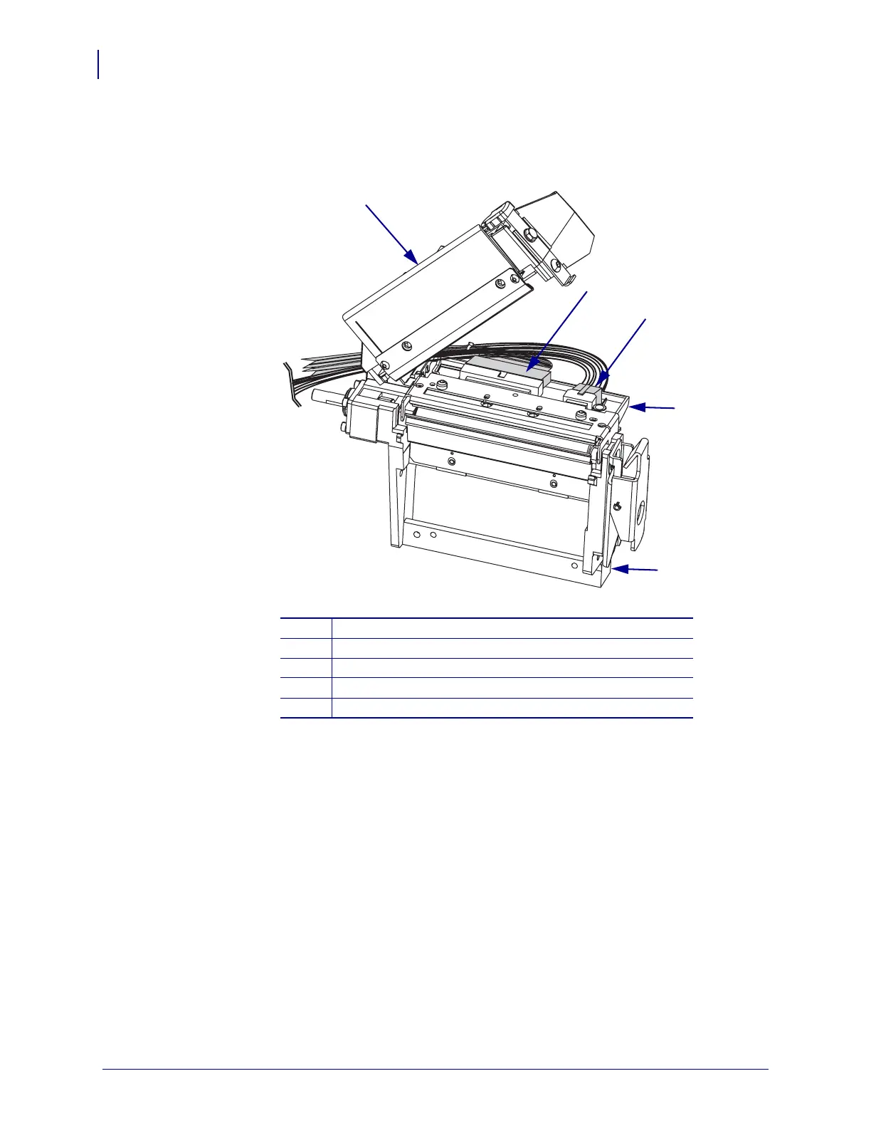
5. See Figure 56. Unlatch the print mechanism, and then lift and latch it in the open position.
Figure 56 • Printhead Removal and Installation
6. Set the printhead onto the bearings of the platen housing.
7. Disconnect the printhead data and power cables.
1
Print mechanism
2
Printhead data cable
3
Printhead power cable
4
Printhead assembly
5
Platen housing
2
1
3
4
5
 Loading...