Corrective Maintenance
Printhead Cables
184
14207L-001 A ZM400/ZM600 Maintenance Manual 8/9/07
11. See Figure 54 on page 176. Rotate the two printhead pressure dials to the desired position
for your daily printing.
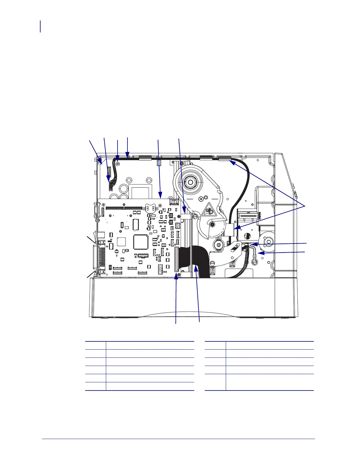
12. See Figure 62. Route the printhead power cable as shown and then connect it to J3 on the
power supply board.
13. Insert the printhead power cable into the two cable clips shown.
14. Ensure that the printhead power cable is routed around the standoff as shown.
Figure 62 • Connect the Printhead Cables
15. Route the printhead data cable connector under the main logic board (MLB) mounting
bracket and then connect it to P19 on MLB.
1
Power supply board
7
Cable clips (2)
2
J3
8
Cable tie
3
Standoff
9
Ground cable
4
Printhead power cable
10
Printhead data cable
5
Main logic board (MLB)
11
P19
6
MLB mounting bracket
2
7
4
11
6
10
8
1
5
3
9
 Loading...