201
Corrective Maintenance
Printhead Pressure Dials
8/9/07 ZM400/ZM600 Maintenance Manual 14207L-001 A
4.
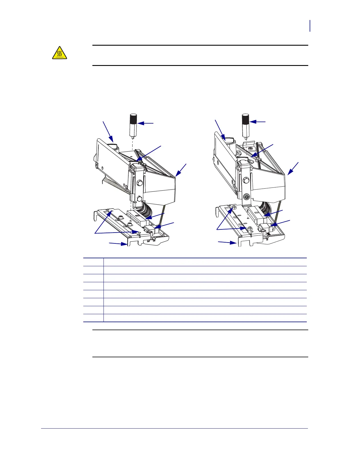
See Figure 72. Remove the printhead thumbscrew.
Figure 72 •
Remove the Printhead and Cable Connections
5.
6.
Slide the printhead fork assembly out of the print mechanism.
7. Disconnect the two printhead cables from the printhead assembly.
8. Remove the printhead assembly and set it aside on the antistatic mat.
Caution • The printhead may be hot and could cause severe burns. Allow the
printhead to cool.
1
Thumbscrew
2
Printhead pressure dial
3
Print mechanism assembly
4
Printhead data cable
5
Printhead power cable
6
Printhead fork assembly
7
Locating holes
8
Locating pins
1
2
2
3
4
5
6
7
1
2
2
3
4
5
6
8
Z4M
Z6M, Z4Mp
us
Z6Mp
us, S4M
ZM400/ZM600
Caution •
While performing any tasks near an open printhead, remove all rings,
watches, hanging necklaces, identification badges, or other metallic objects that could
touch the printhead.
Open the print mechanism, and lift and latch it in the vertical position.
 Loading...