EasyManuals Logo

Zebra ZM400 Series User Manual

Zebra ZM400 Series
470 pages
To Next Page IconTo Next Page
To Previous Page IconTo Previous Page
Page #332 background imageLoading...
Page #332 background image
Corrective Maintenance
Cutter Option
332
14207L-001 A ZM400/ZM600 Maintenance Manual 8/9/07
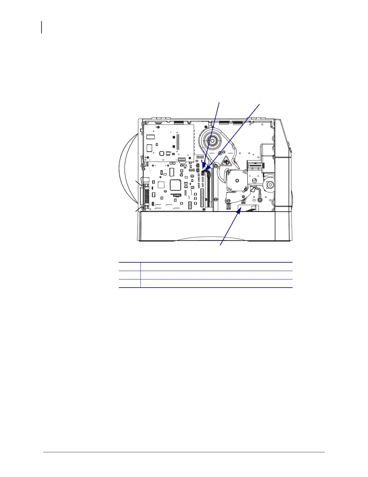
6. See Figure 194. Locate the connector P26 on the main logic board (MLB) and plug in the
cutter assembly connector. Route the cable as shown and ensure that it is away from the
drive belt and gears.
Figure 194 • Locate Cutter Connector on the Main Logic Board
1
Main logic board (MLB) connector, P26
2
Cutter cable connector
3
Access hole
1
2
3

Table of Contents

Questions and Answers:

Question and Answer IconNeed help?

Do you have a question about the Zebra ZM400 Series and is the answer not in the manual?

Zebra ZM400 Series Specifications

General IconGeneral
Max Print Width4.09 inches (104 mm)
Max Print Speed10 inches per second (254 mm per second)
Print MethodThermal Transfer/Direct Thermal
Resolution203 dpi (8 dots/mm)
ConnectivityUSB 2.0, Serial RS-232, Parallel, Internal Ethernet (10/100), optional wireless
Media Width1"/25.4 mm to 4.5"/114 mm
Media Length0.25 to 39 inches (6 to 991 mm)
Media Thickness0.0023"/0.058 mm to 0.010"/0.25 mm
Ribbon Width1"/25.4 mm to 4.33"/110 mm
Ribbon Length1476 feet (450 m)
Supported Media TypesContinuous, die-cut, notch, black-mark
Operating Temperature40°F to 105°F (5°C to 40°C)
Storage Temperature-40°F to 140°F (-40°C to 60°C)

Related product manuals