APPEAR AS Confidential 137/352
7 DECODER OUTPUT CONFIGURATION
The decoder modules are configured using the Decoders view in the Navigation Pane. All available decoder
modules will be listed based on their slot position.
The chassis can hold multiple dual decoder modules. Follow the procedure below to configure the modules.
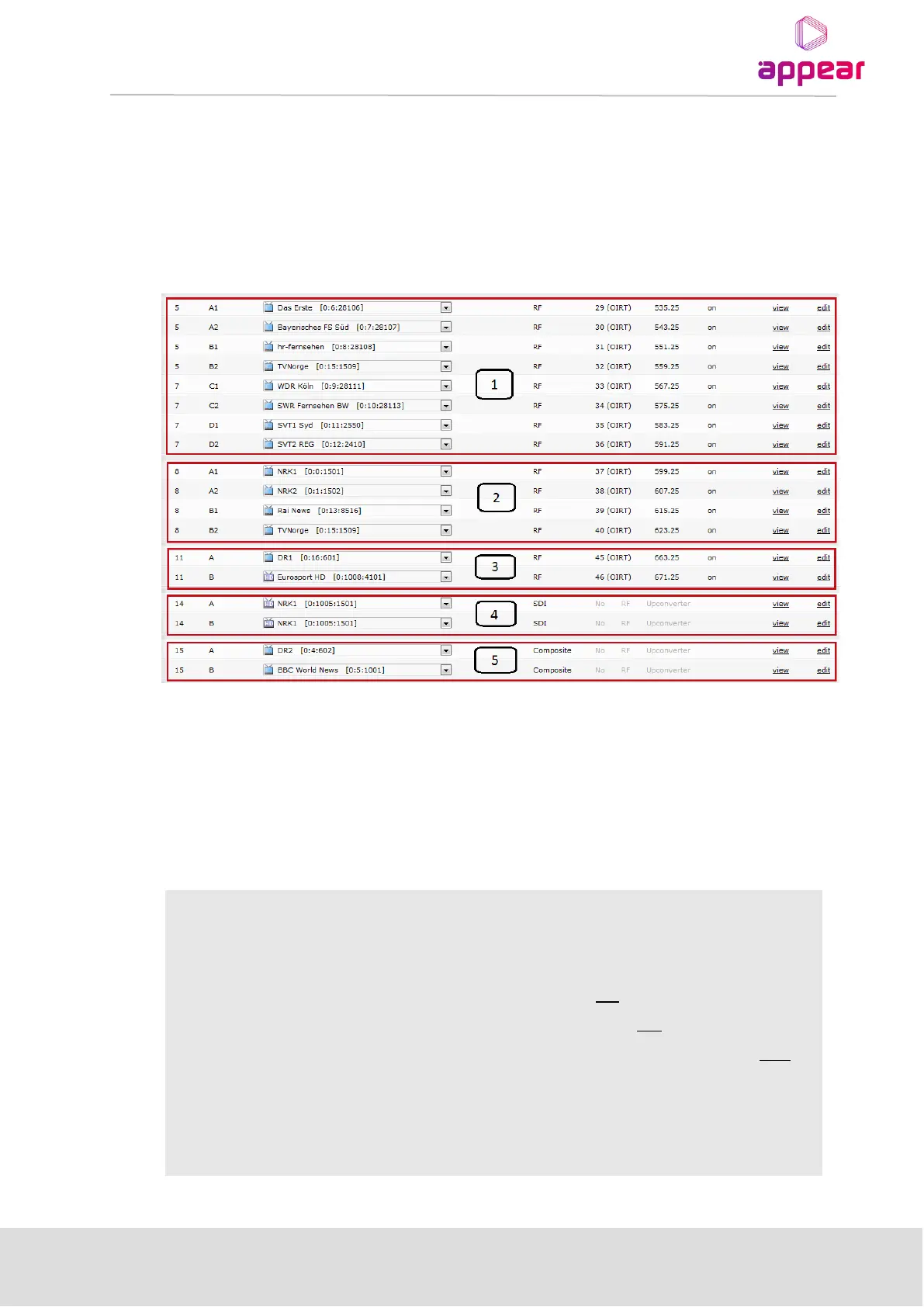
Open the Decoders view in the Navigation Pane and the following will be displayed.
The different types of decoders are displayed in a different way:
1. 8 channel quad decoders with TV modulators (the TV modulator is in slot 7)
2. 4 channel quad decoders with TV modulators
3. Decoders with HP RF modulation and stereo
4. Decoders with SDI outputs
5. Decoder with Composite output
The Decoders page contains the following information:
Slot position in the chassis
Depending on the number of channels in the decoder, the channels are identified
in the following style:
• Channel A and B for decoders with two channels
• Channels A, B, C, and D for decoders with four channels
• Channels A1, A2, B1, B2, C1, C2, D1, and D2 for decoders with eight
channels
Assigns a service to the output. The service list is automatically generated from
the services available on the input modules. For an MPTS input stream, all
available services will be listed. If Service Definition Tables (SDTs) are available in
input streams, the service list will consist of service names together with the