If source is not cloned output then if it is checked then will raised alarm for it.
This option can be used to use Input Redundancy for multicasts from different sources.
When in this module, the resulting stream will not be seamless.
The switching time when ‘No bitrate’ on the main port is 100ms.
12.2 INTERNAL REDUNDANCY
Internal redundancy refers to the process by which select decoder and output modules can receive configuration
from two different MMI boards, but not at the same time. This section describes internal redundancy for these
cards in detail.
The chassis will have two switches/MMI modules. One switch will be configured as the main switch while the
other switch will be configured to be the redundant switch.
The following cards support Internal Redundancy:
• DDM and ADM
• FM Radio
• ASI Output
• IP output
• Dual IP output
• Dual IP Cloned output
• Modulators
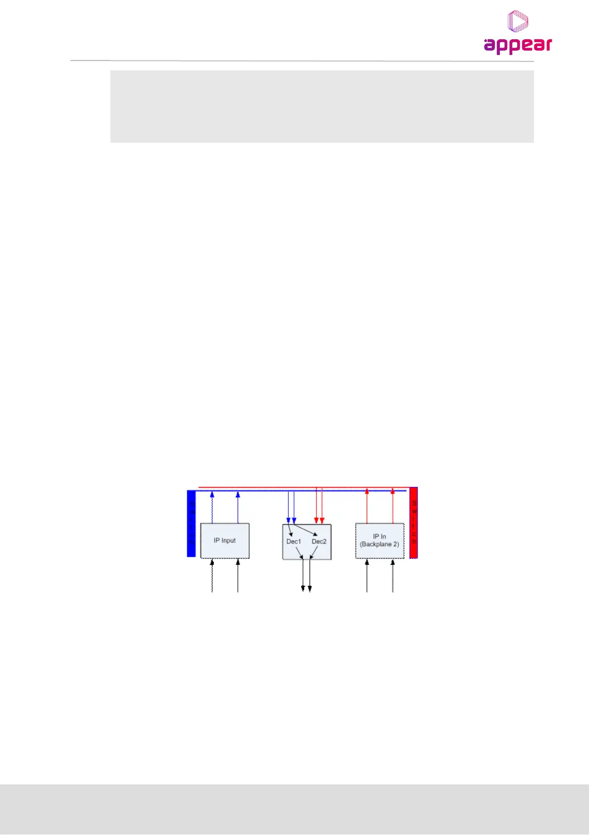
12.2.1 DUAL BACKPLANE CONFIGURATION
The figure below shows the signal flow within the unit when having two backplanes, one MMI card connected to
backplane 1 and second MMI card to backplane 2 respectively.
12.2.2 HARDWARE REQUIREMENTS
The following hardware is required to implement internal redundancy, either:
Two Switch management cards and Two IP input modules
or
Two Switch + IP modules
In addition, one or more output modules are required to implement internal redundancy.