APPEAR AS Confidential 42/352
The 8VSB module is equipped with an electrical connector (RJ45) marked “control” that is not in use. It is not
required to configure the IP address or connect the port to the IP network.
3.3.10 ISDB-T INPUT
Each ISDB-T input module has one 75Ω F connector. The input is distributed to four tuners internally, so each
module can receive four independent frequencies. The maximum input level is -10dBm. The recommended input
level is between -30dBm and -50dBm.
3.3.11 SDI ENCODER
The SDI Encoder module has 4 BNC inputs that vary in functionality depending on the mode. These functions are
as follows:
• SD Encoder – Port A, B, C and D are in SDI mode and link to the 4 corresponding internal encoder ports
• HD Encoder – Port A and B are in HD-SDI mode and link to the 2 corresponding internal encoder ports
• HD + AES Encoder – Ports marked HDSDI A and AES A link to channel A internally while HDSDI B and
AES B link to channel B
• Universal HVQ Encoder – In HD, port A is in HD-SDI mode, in SD, port A and B are in SDI mode
• Universal Dense Encoder- In 4 HD and 4 SD mode.
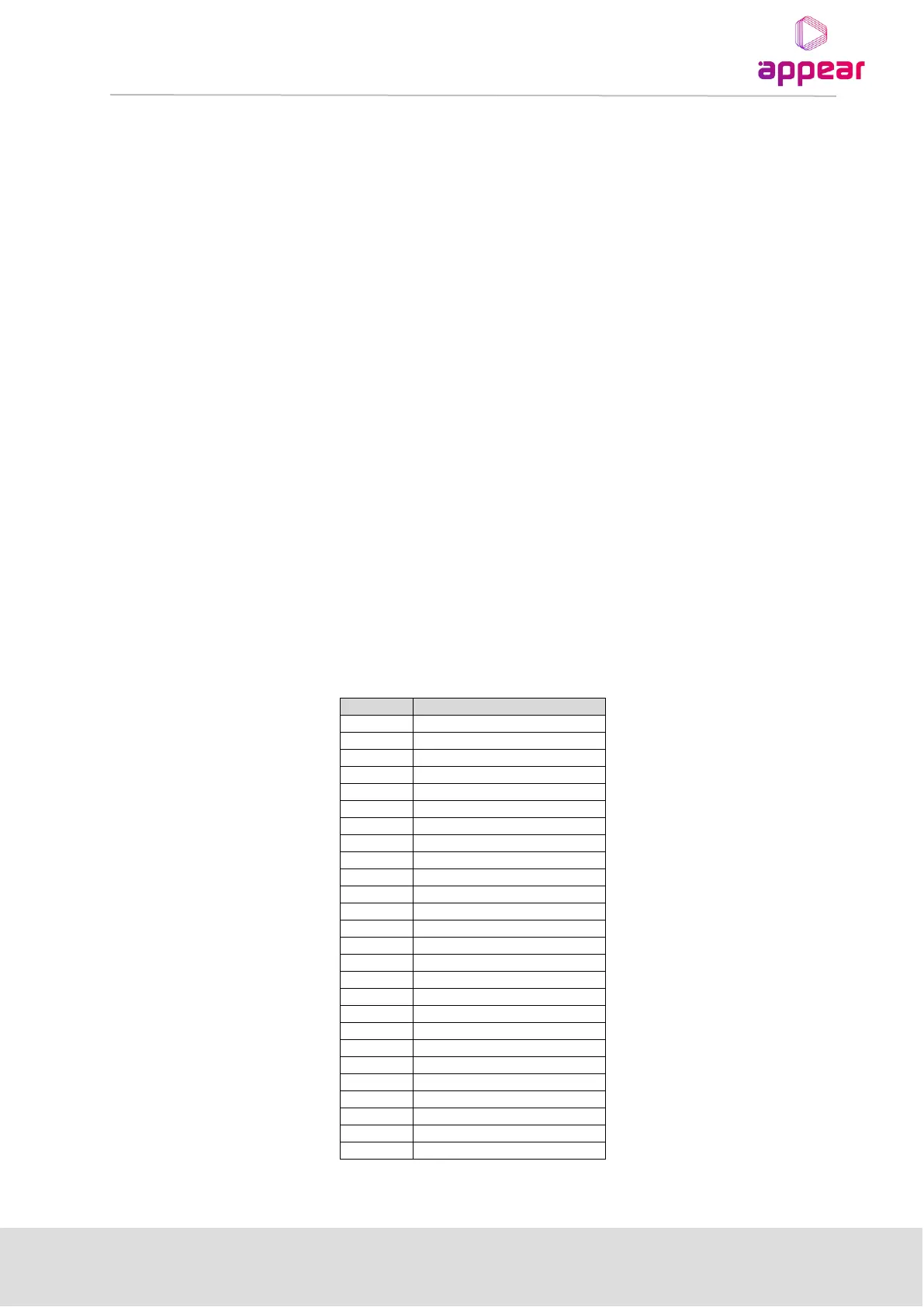
3.3.12 ANALOG ENCODER
The Analog encoder module has 4 High Density BNC input ports which correspond to the internal ports. As well
as this, there is one HD DSUB 26 male connector for audio. The pin-out for this is as follows: