APPEAR AS Confidential 304/352
12.2.3 CONFIGURING MODULES FOR INTERNAL REDUNDANCY
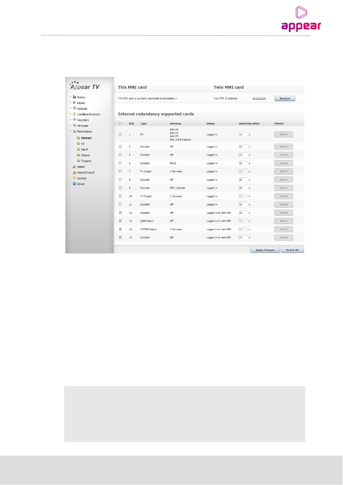
Configuring internal redundancy is done by selecting Redundancy → Internal in the Navigation Pane. This will
load the configuration page displayed below.
There are three sections on the Internal Redundancy configuration page:
This MMI card – displays the status of the MMI module in the chassis. This section is used as an indicator for MMI
correlation. MMI correlation is needed to get rid of the card missing alarms on the spare MMI module. The status
of the MMI module depends on which backplane it is logged in to.
Twin MMI card – displays the status of the Twin MMI card linked to this chassis, if there is one. The IP address of
the redundant MMI module is used to notify the internal redundancy GUI about the module. This other MMI
module is referred to as Twin MMI. Once a Twin MMI is added, both MMI modules will exchange their module
list; all other configuration must be done separately on each MMI module.
Internal redundancy supported cards – displays a list of modules on which internal redundancy is supported,
along with the service name (or number of services for QAM output modules), status, and switching delay. If
internal redundancy is not enabled, the service name value is off.
An alarm with the message Unable to communicate with TWIN MMI is generated whenever connection breaks
between MMI Input cards.