APPEAR AS Confidential 185/352
A component-type PID mapping mode can be set, i.e. the input component type is used to identify the input PID
itself, instead of using the input PID value only. This feature is typically used to provide a fixed PID line-up at the
output, even if the input PID values are changing dynamically at the input.
To achieve component-type PID mapping, a set of mapping rules are applied to the incoming PID which matches
a specific filter. Several rules/filters can be added, and one PID may match more than one rule. However, only one
rule (the one with the higher priority) will be applied to the mapping of the PID.
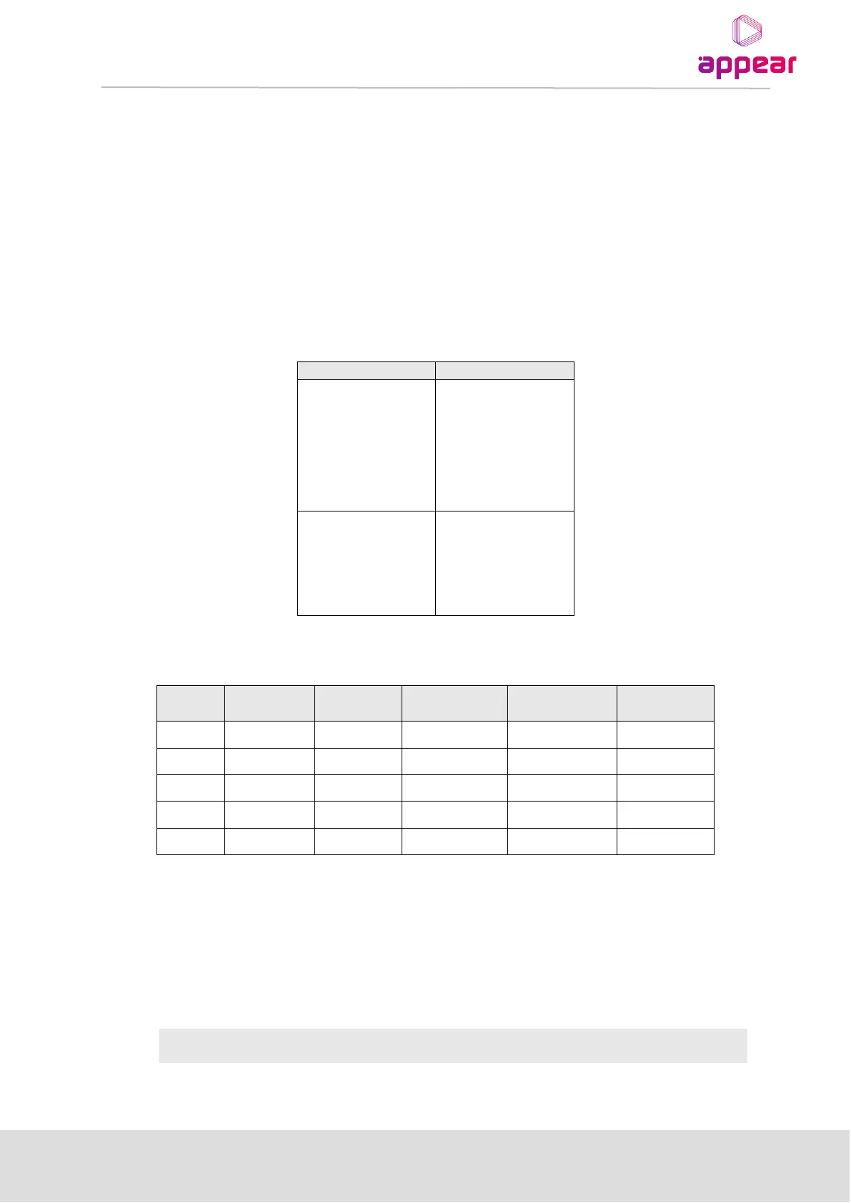
For example:
The default rule will in this example stop the input PID 503 as no rule finds a match. Also the TTX PID will be
stopped during daytime as the input PID does not match the PID based rule.
With many rules potentially being active at the same time, it may be hard to foresee the result. Consequently the
GUI reflects the evaluated output PID line-up dynamically as the rules are defined.
The following manual mapping modes are available: