EasyManua.ls Logo

Appear TV DC100X - Page 197

Default Icon
352 pages
Print Icon
To Next Page IconTo Next Page
To Previous Page IconTo Previous Page
Loading...
APPEAR AS Confidential 197/352
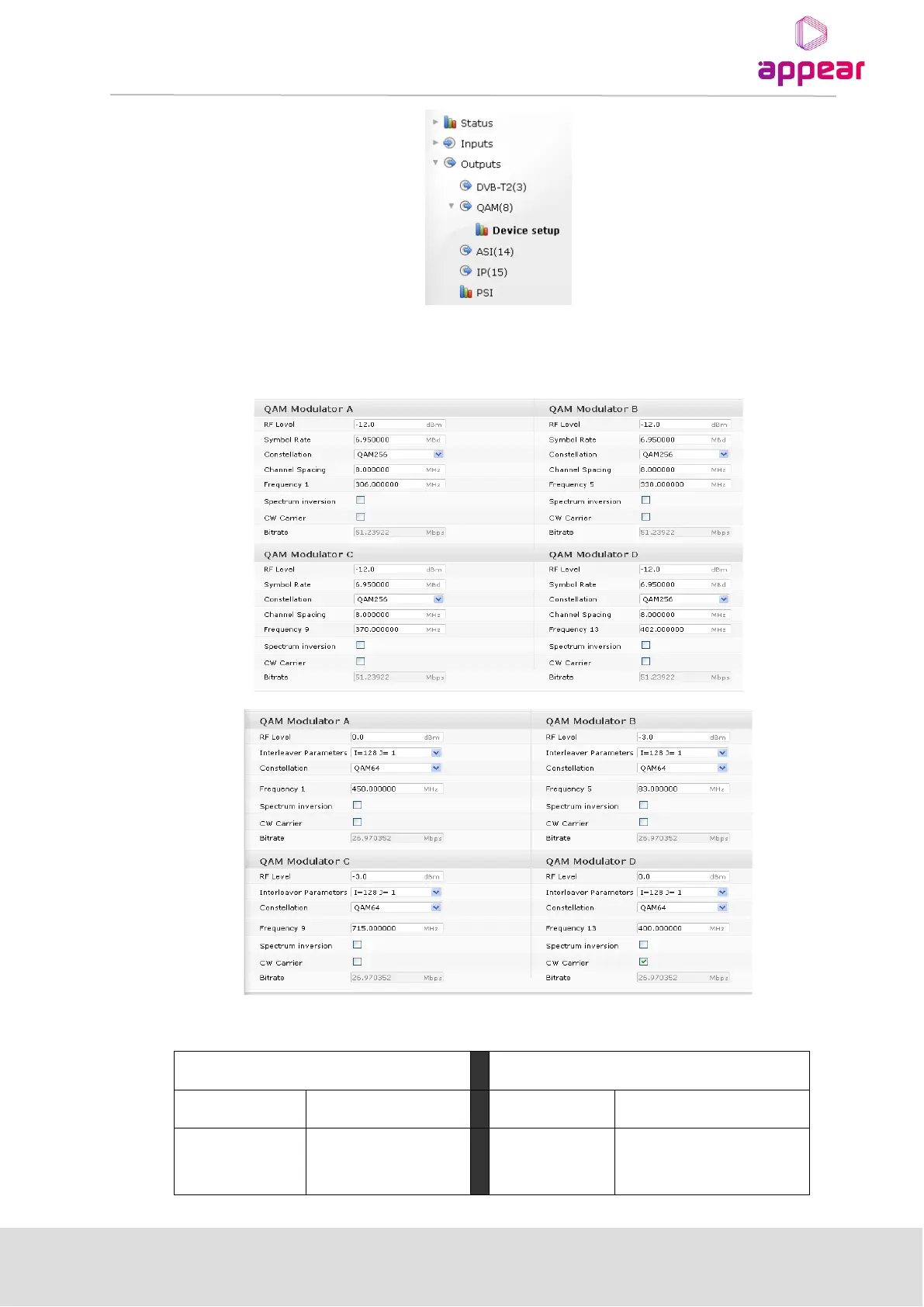
When Device Setup is selected, both modulators can be configured from the resulting dialog. The figures below
show the Device Setup node for Annex A/C and Annex B QAM modulators; correct values for these parameters
can be obtained from respective network operators.
Listed below are the parameter limit-values for the QAM Output Module:
Annex A/C
Annex B
Symbol rate
4.7 7.0 MBd
RF Level
-12 +2.2dBm
RF Level
-12 +2.2 dBm
Interleaver
I
max
= 128
J
max
= 16

Table of Contents

Related product manuals