892-0000010B OM
125
In a hydraulic system, a safety valve, a retarding valve and a filter valve have the
following purpose:
- the safety valve installed in the distributor is designed to protect the HLL from over-
loads by limiting the pressure within the range from 18 to 20 MPa (when the pressure in the
HLL rises above the specified value, oil flow is drained into the tank through the safety valve);
- retarding valve, installed directly in the cylinder, is designed to reduce the speed of
lowering attachments in order to avoid damage to the working bodies on the ground;
- the filter valve, installed in the filter housing, is designed to limit the drain pressure
within the range from 0.3 to 0.4 MPa (if the filter cartridge is clogged, oil flow is drained into
the tank through the filter valve, bypassing the filter);
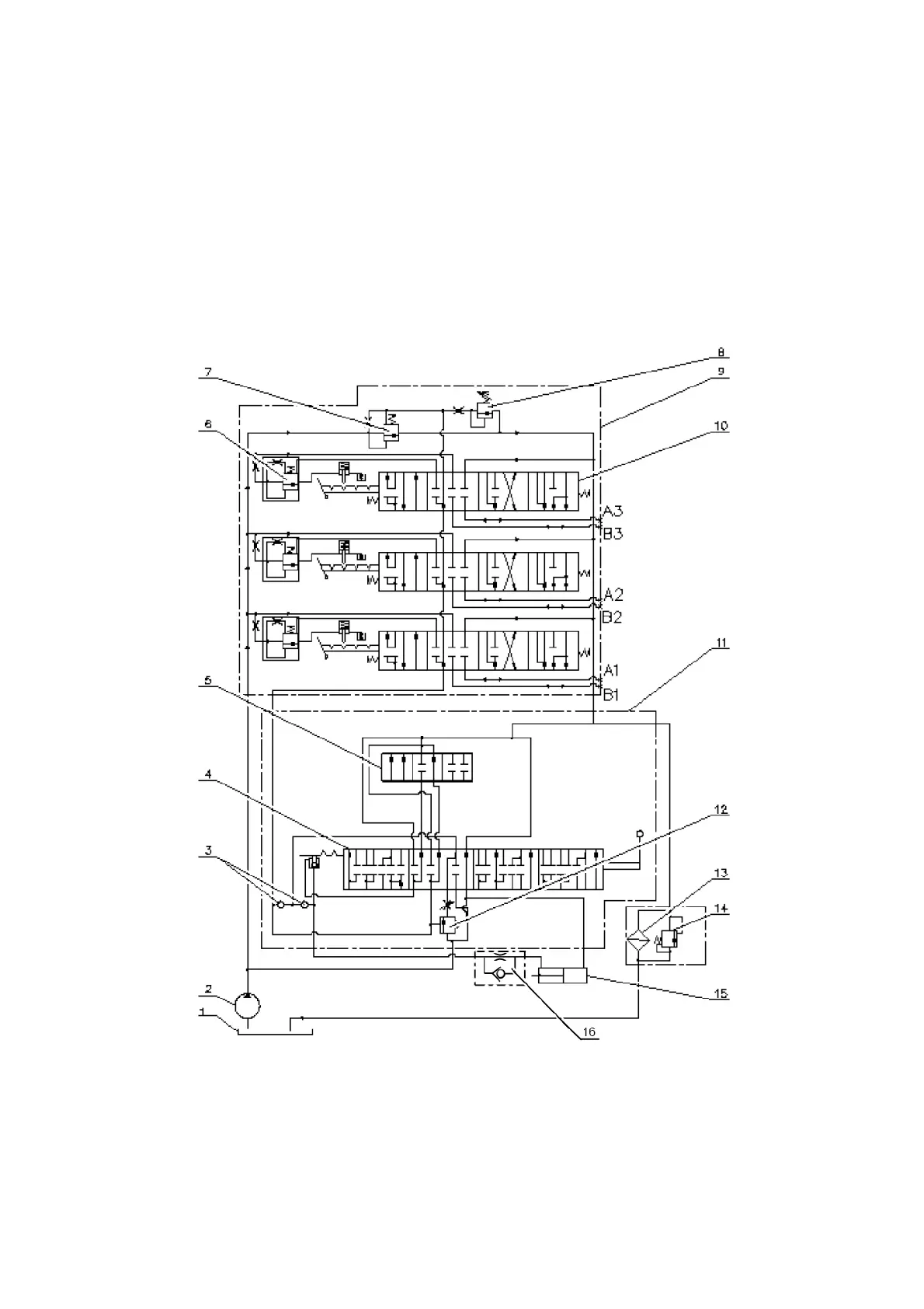
The HLL circuit hydraulic diagram with the R80-3/4-222 distributor installed is shown
in Figure 3.11.2.
1 - tank; 2 - pump; 3 - check valve; 4 - sleeve; 5 - spool; 6 - spool auto-return valve; 7-
overflow valve; 8 - safety valve; 9 - R80-3/4-222-3G distributor; 10 - spool; 11 - draft (positional)
control unit; 12 - priority valve; 13 - hydraulic system filter; 14 - filter valve; 15 - cylinder; 16 -
retarding valve.
Figure 3.11.2 – HLL circuit hydraulic diagram with the R80-3/4-222 distributor in-
stalled