892-0000010B OM
52
Handwheel of the correction speed controller 4 is used to adjust the implement position
correction speed when the tractor is operating. As you turn handwheel 4 clockwise, the speed
of corrections decreases, as you turn it counterclockwise, it increases. Adjust handwheel 4 after
completing the adjustments of the RHL and attachments (plow, cultivator, etc.).
When preparing the unit for operation using the draft control method, do the following:
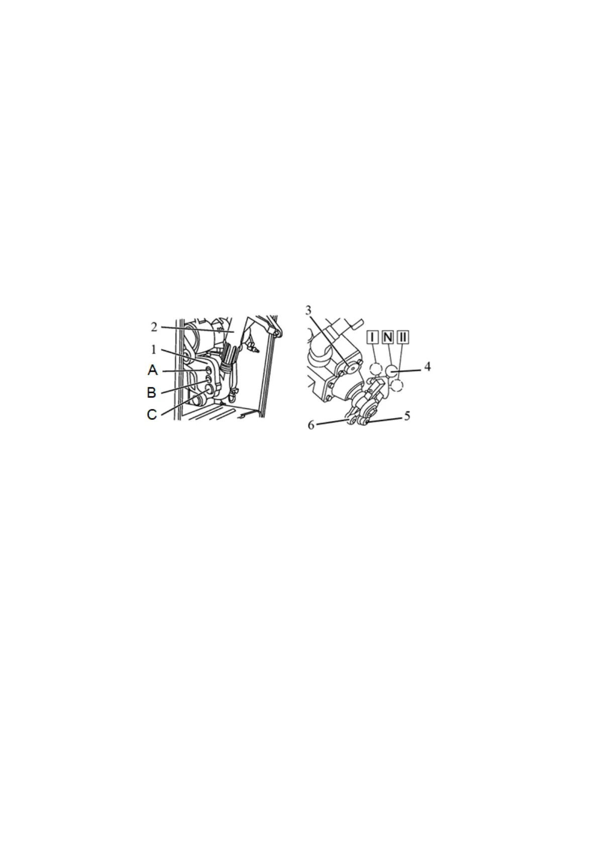
- install upper link 2 (Figure 2.16.2) of the lift linkage on the upper hole of clevis 1 (position
“A” in Figure 2.16.2);
- connect the mounted implement (machine) to the tractor RLL;
- if necessary, adjust the RLL and the attachments.
- engage the draft control method, for which raise the mounted implement (machine) to
the highest position and let switch 4 into the groove of draft lever 5 by turning the switch to the left
(in the direction of the tractor) to position “II”. For easier engagement, before letting the switch into
the groove, move the switch forward (along the direction of the tractor) until it aligns with the
groove on lever 5;
- adjust handwheel of the correction speed controller 3. Turning the handwheel clockwise
decreases the speed of corrections, turning it counterclockwise increases the speed. By turning
the handwheel, achieve smooth automatic depth control during operation. Do not turn the hand-
wheel clockwise until it stops, as this will lead to an excessively slow lifting of the implement (ma-
chine) and cause increased slippage of the tractor drive wheels;
1 – clevis; 2 – upper link; 3 – handwheel of the correction speed controller; 4 – switch
of control method; 5 – grove of draft lever; 6 – groove of position lever.
Figure 2.16.2 – Positions of the control switch and the upper link with the draft con-
trol method
At the beginning of the run, lower the mounted machine by moving handle 2 (Figure
2.16.1) forward. The further forward the handle is set, the greater the depth of tillage is. As
you move handle 2 towards you, the depth will decrease. After adjusting to the required
depth, move limiter 1 along the groove of the console until it stops against the handle and
secure.
At the end of the run, to take the implement out, move handle 2 to the "uplift" position
- pull to yourself up to the stop. After the end of the uplift, the handle should return to the
neutral position "N" by itself.
At the beginning of each subsequent run, lower the implement by moving handle 2
forward until it stops against limiter 1.
During plowing, in cases where the resulting depth is insufficient after you have the
moved the draft control handle forward to the maximum depth, relocate upper link 2 of the
attachment to the middle hole of clevis 1 (position "B" in Figure 2.16.2);
The adjustment of the handwheel of the correction speed and the choice of the hole
in the clevis when installing the upper link should be carried out for specific soil conditions
and each type of agricultural machinery. Changeovers are not required in the course of work.