737 Flight Crew Operations Manual
Flight Management, Navigation -
Controls and Indicators
Boeing Proprietary. Copyright © Boeing. May be subject to export restrictions under EAR. See title page for details.
D6-27370-866-EGP 11.10.23
3 Transfer (TFR) Switch
TFR – STANDBY frequency moved to ACTIVE frequency; ACTIVE frequency
moved to STANDBY frequency.
4 Frequency Selector
Rotate – manually selects the standby frequency.
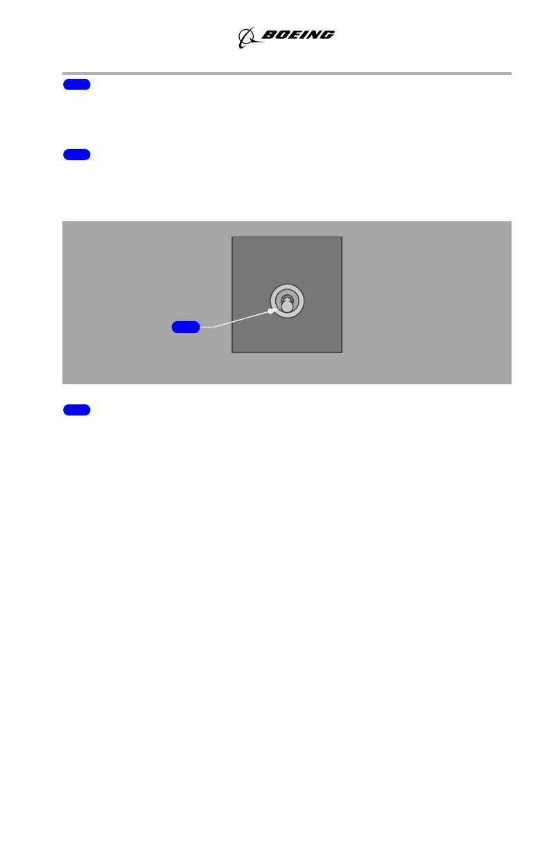
VHF NAV Transfer Switch
1 VHF NAV Transfer Switch
The VHF NAV transfer switch changes the source of the data that the DEUs use
for the navigation displays. The switch transfers the following data: DME, ILS,
VOR, and MCP course.
BOTH ON 1 – the DEUs use Multimode Receiver 1 as the source for the captains
display and first officers display.
NORMAL – Multimode Receiver 1 supplies data for the captains display and
Multimode Receiver 2 supplies data for the first officers display.
BOTH ON 2 – the DEUs use Multimode Receiver 2 as the source for the captains
display and first officers display.
Note: The Digital Flight Control System cannot use VOR/ILS data that is not
shown on the displays. Thus, when the Autopilot (A/P) system is engaged
the VHF Navigation Control must match the primary Autopilot system that
is ENGAGED for proper ILS/VOR operations; i.e. (CMD A uses VHF
NAV 1 for control and CMD B uses VHF NAV 2 for control).
VHF NAV
NORMAL
BOTH BOTH
ON 2
ON 1
September 15, 2016