737 Flight Crew Operations Manual
Flight Instruments, Displays Chapter 10
Head-Up Display System, Symbology Section 42
Boeing Proprietary. Copyright © Boeing. May be subject to export restrictions under EAR. See title page for details.
D6-27370-866-EGP 10.42.1
This Section Applies to YK981 - YQ456
42 Head-Up Display System, SymbologyHead-Up Display System, SymbologyFile Highlig ht
Introduction
HUD symbology consists of green symbols projected on the combiner from the
OHU. The PRI mode display symbols are similar to those on the CDS, and can be
used for all phases of flight. The approach mode displays (AIII, IMC, VMC) are
optimized to enhance aircraft control and situational awareness during final
approach, flare, and touchdown.
In addition to flight symbology, TCAS resolution advisories and HUD system
failure flags and data source annunciations are displayed when active.
Head-Up Guidance Display Symbology
The following symbols can be displayed on the combiner, depending on HUD and
EFIS control panel switch selections.
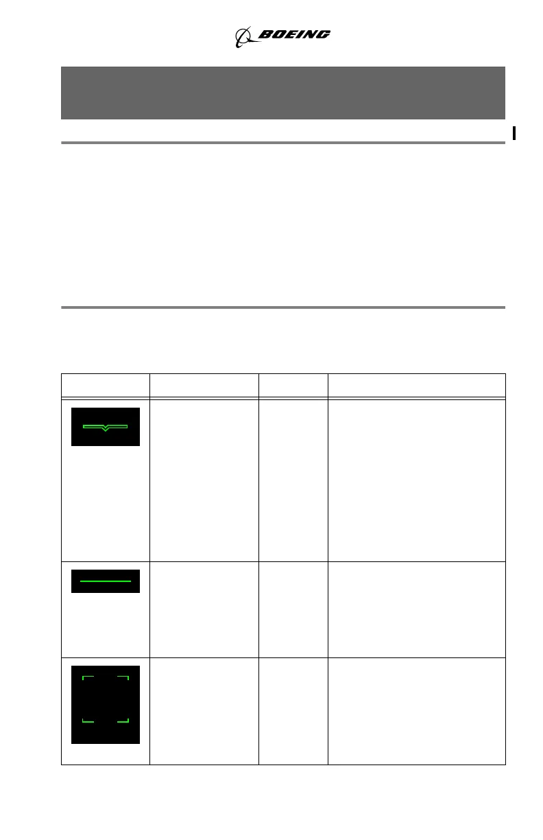
SYMBOL NAME MODE REMARKS
Airplane
reference
All Top center point of the symbol
represents airplane projected
centerline. The symbol is
positioned at a fixed position 7
° above the display’s vertical
center.
Symbol is fixed at display
center when the unusual
attitude display is active.
Horizon Line All Indicates the horizon relative
to the airplane reference
symbol.
Position based on current
airplane pitch and roll attitude.
Pitch Scale PRI in
flight,
AIII
approach,
IMC,
VMC
Displays airplane pitch in five
degree increments between
-20 ° and +25 °.
September 15, 2016