737 Flight Crew Operations Manual
Fire Protection Chapter 8
Controls and Indicators Section 10
Boeing Proprietary. Copyright © Boeing. May be subject to export restrictions under EAR. See title page for details.
D6-27370-866-EGP 8.10.1
10 Controls and IndicatorsControls and IndicatorsFile Highlight
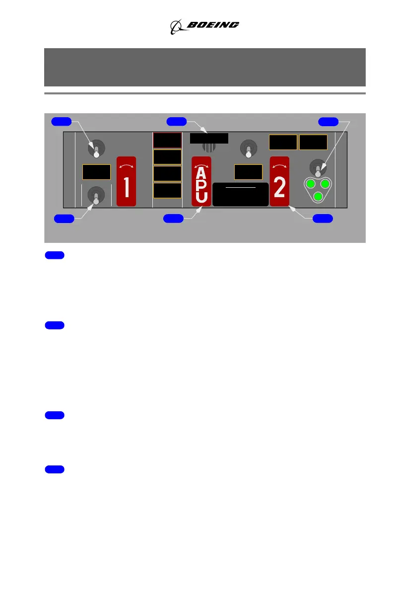
Overheat/Fire Protection Panel Switches
1 Overheat Detector (OVHT DET) Switch
NORMAL – detection loop A and loop B are active.
A – detection loop A is active.
B – detection loop B is active.
2 Fire Warning BELL CUTOUT Switch
Push –
• extinguishes both master FIRE WARN lights
• silences the fire warning bell
• silences the remote APU fire warning horn (on the ground only)
• resets the system for additional warnings.
3 Extinguisher (EXT) TEST Switch
(spring–loaded to center)
1 or 2 – tests bottle discharge circuit continuity for all three extinguisher bottles.
4 Fault/Inoperative (FAULT/INOP) and
Overheat/Fire (OVHT/FIRE) TEST Switch
(spring–loaded to center)
FAULT/INOP – tests fault detection circuits for both engines and the APU.
OVHT/FIRE – tests overheat and fire detection loops on both engines and APU,
and wheel well fire detector
Note: See Fire and Overheat Detection System Fault Test in Section 20.
DISCHARGE
APU BOTTLE
INOP
APU DET
FAULT
WELL
WHEEL
PULL WHEN ILLUMINATED
OVERHEAT
R
ENGINES
OVHT DET
NORMAL
B
A
12
T
S
E
T
T
X
E
E
R
I
F
T
H
V
O
P
O
N
I
DISCH
ENG 2
(FUEL SHUTOFF)
FIRE SWITCHES
OVERHEAT
ENG 1
OVHT DET
A
L
DISCH
LOCK OVERRIDE: PRESS
RL
DISCH
BUTTON UNDER HANDLE
L
R
DISCHARGEDISCHARGE
R BOTTLE
T
L
U
A
F
TEST
L BOTTLE
APU
BELL CUTOUT
NORMAL
B
21
5
4
6
AFT ELECTRONIC PANEL
3
March 18, 2011