737 Flight Crew Operations Manual
Flight Controls -
Controls and Indicators
Boeing Proprietary. Copyright © Boeing. May be subject to export restrictions under EAR. See title page for details.
9.10.12 D6-27370-866-EGP
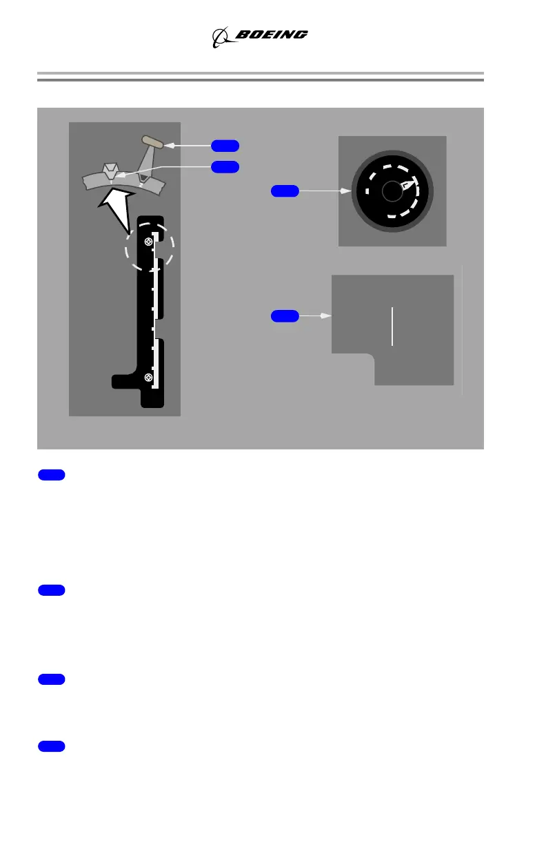
Trailing Edge Flaps
1 FLAP Lever
• selects position of flap control valve, directing hydraulic pressure for
flap drive unit
• position of the LE devices is determined by selecting TE flap position
• flap lever positions 10, 15, 25, 30, and 40 arms the flap load relief
system.
2 Flap Gates
Prevents inadvertent flap lever movement beyond:
• position 1 - to check flap position for one engine inoperative go-around
• position 15 - to check flap position for normal go-around.
3 Flap Position Indicator
• indicates position of left and right TE flaps
• provides TE flaps asymmetry and skew indication.
4 FLAPS LIMIT Placard
Indicates maximum speed for each flap setting.
FLAP
UP
0
1
2
5
10
15
25
30
40
HORN
CUTOUT
FLAP
DOWN
1-250K
2-250K
5-250K
10-210K
15-200K
30-175K
25-190K
FLAPS LIMIT (IAS)
40-162K
230K ALT FLAP
EXTEND
1-250K
2-250K
5-250K
10-210K
15-200K
30-175K
25-190K
FLAPS LIMIT (IAS)
40-162K
230K ALT FLAP
EXTEND
CONTROL STAND
4
3
1
CENTER FORWARD
PANEL
2
September 24, 2015