737 Flight Crew Operations Manual
Electrical -
System Description
Boeing Proprietary. Copyright © Boeing. May be subject to export restrictions under EAR. See title page for details.
D6-27370-866-EGP 6.20.7
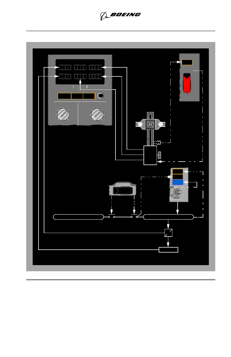
Electrical Power Controls and Monitoring Schematic
DC Power System
28 volt DC power is supplied by three TR units, which are energized from the AC
transfer busses. The battery provides DC power to loads required to be operative
when no other source is available.
On the ground, an amber ELEC light comes on to indicate that a fault exists in DC
power system or standby power system. The ELEC light is inhibited in flight.
CPS FREQ
DC AMPS
MAINT
ELECTR UNIT
APU GEN
GEN2
GEN1
GRD
PWR
INV
TEST
STBY
PWR
BAT
DISCHARGE
AC VOLTS
TR1
TR2
TR3
TEST
BAT
BUS
BAT
TR3
STBY
PWR
DISCONNECT
CONDITION: ENGINE DRIVEN GENERATORS ON AC BUSSES
IDG2
AIR
FAN
GENERATOR 1
FROM
GEN 2
OFF
ON
TR2
AC TRANSFER BUS 2
AC TRANSFER BUS 1
BUS
GEN OFF
OFF
SOURCE
BUS OFF
TRANSFER
DRIVE
2
BUS TRANSFER
F
O
U
A
F
O
T
DC VOLTS AC AMPS
DC BUS 2
May 15, 2008