737 Flight Crew Operations Manual
Engines, APU Chapter 7
APU System Description Section 30
Boeing Proprietary. Copyright © Boeing. May be subject to export restrictions under EAR. See title page for details.
D6-27370-866-EGP 7.30.1
30 APU System DescriptionAPU System DescriptionFile Highlight
Introduction
The auxiliary power unit (APU) is a self–contained gas turbine engine installed
within a fireproof compartment located in the tail of the airplane.
The APU supplies bleed air for engine starting or air conditioning. An AC
electrical generator on the APU provides an auxiliary AC power source.
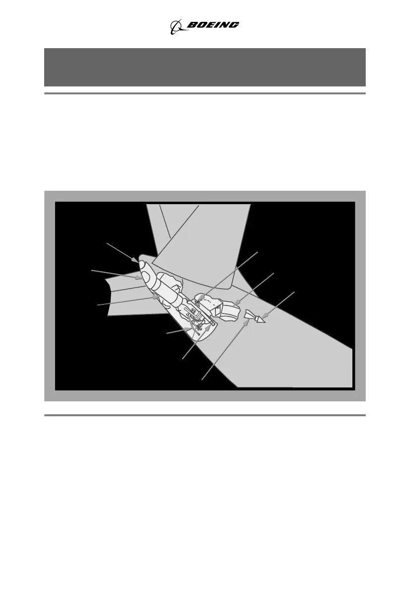
APU Location
APU Operation
The APU starts and operates up to the airplane maximum certified altitude.
The APU supplies bleed air for both air conditioning packs on the ground or one
pack in flight. Both transfer busses can be powered on the ground or in flight.
APU Fuel Supply
Fuel to start and operate the APU comes from the left side of the fuel manifold
when the AC fuel pumps are operating. If the AC fuel pumps are not operating,
fuel is suction fed from the No. 1 tank. During APU operation, fuel is
automatically heated to prevent icing.
AIR DIFFUSER
VORTEX
AIR INLET DOOR
APU BLEED
AIR DUCT
EXHAUST
COOLING AIR
APU DUCT
INLET
DUCT
GENERATOR
OUTLET
APU FUEL
LINE
EXHAUST
MUFFLER
September 26, 2013