737 Flight Crew Operations Manual
Hydraulics Chapter 13
System Description Section 20
Boeing Proprietary. Copyright © Boeing. May be subject to export restrictions under EAR. See title page for details.
D6-27370-866-EGP 13.20.1
20 System DescriptionSystem DescriptionFile High light
Introduction
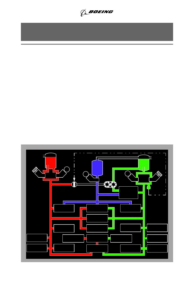
The airplane has three hydraulic systems: A, B and standby. The standby system
is used if system A and/or B pressure is lost. The hydraulic systems power the
following airplane systems:
Either A or B hydraulic system can power all flight controls with no decrease in
airplane controllability.
Each hydraulic system has a fluid reservoir located in the main wheel well area.
System A and B reservoirs are pressurized by bleed air. The standby system
reservoir is connected to the system B reservoir for pressurization and servicing.
Pressurization of all reservoirs ensures positive fluid flow to all hydraulic pumps.
Hydraulic Power Distribution Schematic
• flight controls
• leading edge flaps and slats
• trailing edge flaps
• landing gear
• wheel brakes
• nose wheel steering
• thrust reversers
• autopilots.
AILERONS
ELEV FEEL
ELEVATOR AND
DAMPER
YAW
AIR
PRESSURE
M
M
PTU CONTROL
VALVE
AIR
PRESSURE
POWER
TRANSFER
UNIT
STEERING
NOSE WHEEL ALTERNATE NOSE
WHEEL STEERING
SYSTEM
STBY
SYSTEM
B
SYSTEM
A
NORMAL
BRAKES
FLIGHT
SPOILERS
AUTOPILOT B
TRAILING
EDGE FLAPS
RIGHT THRUST
REVERSER
AND
LEADING EDGE
FLAPS & SLATS
AUTO SLATS
FLIGHT
SPOILERS
RUDDER
LEFT THRUST
REVERSER
GROUND
SPOILERS
AUTOPILOT A
ALTERNATE
BRAKES
LANDING GEAR
TRANSFER UNIT
LANDING
GEAR
M
September 25, 2009