737 Flight Crew Operations Manual
Flight Management, Navigation -
Controls and Indicators
Boeing Proprietary. Copyright © Boeing. May be subject to export restrictions under EAR. See title page for details.
D6-27370-866-EGP 11.10.25
6 Transponder (XPNDR) FAIL Light
Illuminated (amber):
• indicates transponder malfunction or
• ADS-B (if installed) inoperative.
7 Altitude (ALT) SOURCE Selector
1 – enables altitude reporting from air data computer No. 1.
2 – enables altitude reporting from air data computer No. 2.
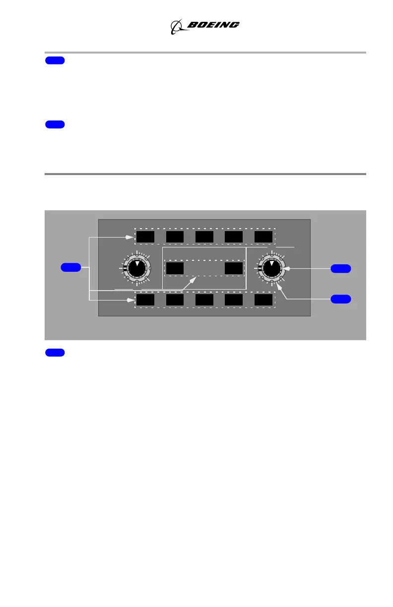
Weather Radar Panel
(SB Changes YK981 - YK992)
1 Weather Radar Mode Switches
Push – selects mode. Left mode switches control the Captain’s radar display, right
mode switches control the First Officer’s radar display.
• TFR (transfer) – transfers other map display selections to related map.
Note: Selecting both TFR switches at the same time results in the TEST
mode test pattern being displayed until one of the TFR switches is
deselected.
• WX – displays weather radar returns without turbulence information.
• WX+T (turbulence) – displays weather radar returns and turbulence.
Turbulence is displayed out to 40 nm for all selected ranges.
Note: Turbulence detection requires presence of detectable precipitation.
Clear air turbulence cannot be detected by radar.
• MAP – displays both ground and weather returns without turbulence
information.
• GC – temporarily displays ground clutter when radar is in auto mode.
WX
GC
AUTO
LEFT
TFR
TILT
UP
15
5
W
0
5
DN
15
GAIN
WX
TFR
X
R
D
R
MAP
TEST
WX+T
MAP
WX+T
DN
TILT
5
0
UP
15
5
15
RIGHT
GC
AFT ELECTRONIC PANEL
1
2
3
GAIN
September 15, 2016